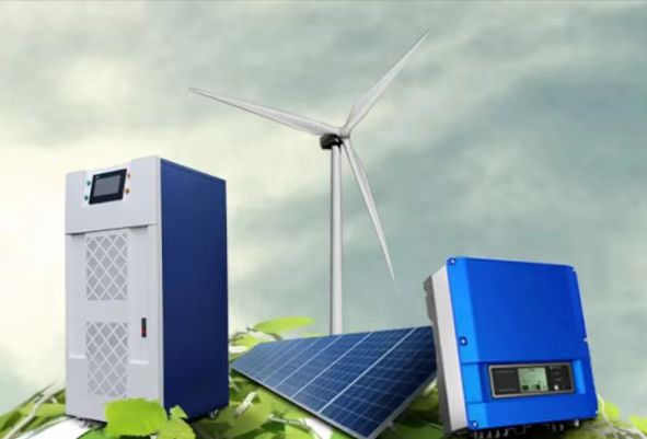

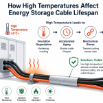

The global shift toward high-density Energy Storage Systems (BESS) has accelerated the transition from traditional air cooling to advanced liquid cooling thermal management. For multi-megawatt containerized energy storage, maintaining optimal battery cell temperatures is critical to preventing thermal runaway, extending cycle life, and ensuring system safety.
Within the liquid cooling fluid loop, Liquid Cooling Quick Couplings (also known as Quick Disconnects, or QDs) serve as the critical hardware interface. Whether for initial factory assembly, system integration, or aftermarket maintenance and modular replacement, choosing the correct fluid connector is a high-stakes decision. A single failure can lead to dielectric coolant leaks, short circuits, or catastrophic system downtime.
This comprehensive engineering guide explores the essential selection criteria for liquid cooling quick couplings specifically tailored for the ESS middleware and aftermarket sectors.
1. Why Quick Couplings Dictate BESS Aftermarket and Maintenance Efficiency
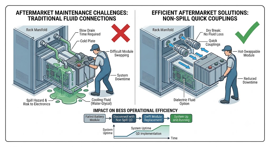
In utility-scale energy storage architectures, battery racks are divided into modular packs. If a battery cell or a liquid cold plate fails within a pack, field technicians must replace the module swiftly.
[Traditional Hard Piping] ──> Requires system draining ──> Long downtime ──> High risk of coolant spill
[Quick Disconnect Couplings] ──> Hot-swappable modules ──> Zero leakage ──> Minutes to service
Using high-quality non-spill quick couplings transforms the serviceability of a BESS site:
- Hot-Swappable Maintenance: Technicians can disconnect and replace a single battery tray without draining the entire cooling loop or shutting down the whole container.
- Leak-Free Operations: Advanced internal valve designs isolate the fluid immediately upon disconnection, protecting sensitive electronics from coolant exposure.
- Reduced Total Cost of Ownership (TCO): Minimizing fluid loss during aftermarket servicing drastically lowers long-term operational overhead.
2. Key Technical Selection Criteria for ESS Liquid Cooling QDs
When engineering or sourcing quick disconnect couplings for energy storage cold plates and manifolds, five core technical parameters must be harmonized.
2.1 Flow Rate and Pressure Drop Optimization
The primary goal of a liquid cooling loop is efficient heat extraction. Every component in the fluid path introduces flow resistance,
A high pressure drop forces the system’s coolant pumps to work harder, consuming parasitic power and lowering the overall energy efficiency (increasing the system PUE).
- The Selection Rule: Look for high-flow, low-profile internal valve designs (such as specialized flush-face or streamlined poppet valves) that minimize fluid turbulence and keep pressure drop to an absolute minimum at standard operational flow rates (e.g., 5 to 30 L/min per rack line).
2.2 Fluid Compatibility and Coolant Type
The aftermarket supplier must know exactly what thermal fluid is running through the BESS tubes. The coupling body material and internal O-rings must possess perfect chemical compatibility with the coolant to prevent degradation or contamination.
- Water-Glycol Mixtures (EGW/PGW): The most common choice. Requires seals that resist ethylene or propylene glycol at elevated temperatures.
- Dielectric Fluids (Immersion / Direct Cooling): Synthetic oils or fluorinated liquids used in cutting-edge direct-contact liquid cooling. They require specific fluorocarbon or specialized elastomer seals to prevent swelling.
2.3 Working Pressure and Burst Pressure Ratings
BESS cooling loops typically operate at relatively low working pressures, generally between 2 bar to 6 bar (30 to 90 PSI). However, during system start-up, thermal expansion, or pump cycling, the system can experience significant pressure spikes (water hammer effect).
- Safety Margin: Ensure the selected quick coupling features a working pressure rating of at least 10 bar (145 PSI), with a burst pressure rating exceeding 30 bar to handle unexpected pressure surges without catastrophic failure.
2.4 Temperature Range Durability
Battery thermal management requires the fluid loop to operate reliably in harsh outdoor environments—from sub-zero arctic deployments to desert solar-plus-storage stations. The quick coupling must maintain its structural and sealing integrity across a typical temperature spectrum of -30°C to +80°C.
3. Material Selection Matrix for Energy Storage Quick Disconnects
Choosing the base metal and sealing elastomer dictates the longevity of the fluid connection. For the energy storage middleware and aftermarket sector, balancing performance against cost is vital.
| Coupling Body Material | Pros | Cons | Ideal BESS Application |
| Engineered Polymers (PPS / PVDF) | Ultra-lightweight, 100% corrosion-free, excellent electrical insulation. | Lower pressure limits, susceptible to cross-threading over multiple cycles. | Pack-level connections, cost-sensitive residential or commercial ESS. |
| Nickel-Plated Brass | Economical, robust, excellent wear resistance during repeated connects. | Heavier than polymer or aluminum, potential galvanic risks if plating chips. | Liquid cooling manifolds, rack-level distribution lines. |
| Stainless Steel (316L) | Ultimate corrosion resistance, highest pressure rating, maximum lifespan. | Highest cost, heavy weight. | Central Cooling Distribution Units (CDUs), harsh marine/offshore BESS setups. |
The Critical Role of Seal Selection (O-Rings)
The metal body holds the pressure, but the elastomer seal holds back the liquid.
- EPDM (Ethylene Propylene Diene Monomer): The absolute gold standard for water-glycol mixtures. It offers phenomenal resistance to glycol solutions within the BESS temperature window. Note: Never use EPDM with petroleum-based dielectric fluids.
- FKM / Viton: Excellent for dielectric fluids, synthetic oils, and higher temperature thresholds, though less flexible at extreme sub-zero temperatures.
4. Valve Design Architecture: Non-Spill Flush-Face vs. Poppet Valves
The internal valving mechanism determines how much fluid escapes during an aftermarket disconnect event.
Flush-Face / Dry-Disconnect Technology (Recommended)
Flush-face (flat-face) quick couplings feature a smooth, flat interface when disconnected.
- Zero Inclusion: When connecting, they prevent air bubbles from entering the cooling loop.
- Zero Spillage: When disconnecting, they limit fluid loss to a mere fraction of a drop (often $< 0.05$ mL). This is critical for BESS aftermarket maintenance, as it eliminates the risk of coolant dripping onto live battery terminals or electronic control units (BMS).
Traditional Poppet Valves
Poppet valves utilize a cone-shaped valve design. While highly reliable and cost-effective for hydraulic systems, they trap a small pocket of fluid between the two halves when coupled. Upon disconnection, this trapped fluid spills out.
- The Verdict: Poppet valves are generally not recommended for pack-level or rack-level liquid cooling due to the high risk of conductive fluid spillage near electrical components.
5. Implementation Types: Manual Snap-In vs. Blind-Mate Rack Configurations
Depending on where the quick coupling is located in the energy storage enclosure, the mechanical mating mechanism varies.
5.1 Manual Slide-to-Connect / Button-Release QDs
These are used at the front or top of battery modules where access is clear. Technicians manually push the coupling halves together until an audible “click” indicates a secure, locked connection. Disconnection is achieved via a simple thumb latch or slide sleeve.
- Aftermarket Benefit: Highly visible, easy to service with standard tools, low mechanical complexity.
5.2 Blind-Mate (Rack-Level Alignment) Couplings
In ultra-dense containerized BESS designs, battery trays are slid into massive racks on guide rails. The quick couplings are mounted on the rear of the battery pack and automatically engage with the cooling manifold at the back of the rack when the tray is pushed home.
- Key Requirement: Blind-mate QDs must feature integrated radial and axial misalignment tolerance (float allowance). As the heavy battery tray slides in, the coupling halves must self-align up to 1mm to 2mm without binding or cross-threading, ensuring a perfect seal every time.
6. Preventing Galvanic Corrosion in the Aftermarket Fluid Loop
A major issue faced by BESS aftermarket operators is fluid loop contamination caused by galvanic corrosion.
Liquid cooling cold plates inside battery packs are frequently made of aluminum due to its excellent thermal conductivity. If a technician installs a raw brass or copper quick disconnect coupling directly onto or adjacent to an aluminum component within a conductive fluid path, a galvanic cell is created. The aluminum acts as an anode and will rapidly corrode, causing pinhole leaks inside the battery pack.
Aftermarket Mitigation Strategies:
- Material Matching: Match the quick coupling material family to the rest of the loop components where possible.
- Surface Treatments: Utilize high-quality anodized coatings or premium nickel-plating on brass connectors to act as an electrical barrier.
- Dielectric Isolators: Install non-conductive plastic or composite fittings as transition pieces between mismatched metals to break the electrical pathway.
- Coolant Monitoring: Regularly test the chemical inhibitors in the water-glycol mixture during routine maintenance to ensure the fluid remains non-conductive.
7. BESS Aftermarket Checklist for Sourcing Liquid Cooling QDs
For procurement managers, middleware integrators, and maintenance engineers upgrading or replacing parts in an existing energy storage asset, use this quick checklist before placing an order:
- [ ] Verify Internal Valve Type: Is it a true flat-face non-spill design to safeguard electrical components?
- [ ] Check Flow Coefficient ($C_v$ / $K_v$): Does the connector match the rack manifold’s flow budget without spiking pump pressure?
- [ ] Validate Seal Compatibility: Is the O-ring rated for the specific brand/mix of glycol or dielectric fluid present in the system?
- [ ] Confirm Misalignment Tolerance: (For blind-mate systems) Does the connector offer enough mechanical “float” to absorb cabinet manufacturing tolerances?
- [ ] Evaluate Locking Safety Mechanisms: Does the manual coupling have a locking sleeve or safety pin to prevent accidental disconnection during thermal vibration?
Frequently Asked Questions (FAQ) for Search Engine Optimization
Q1: What causes a liquid cooling quick coupling to leak in an energy storage system?
The most frequent causes of leaks in BESS quick disconnects are seal degradation due to chemical incompatibility (e.g., using nitrile seals with glycol), particulate contamination blocking the valve seat, or mechanical stress resulting from poor alignment in blind-mate racking systems.
Q2: Can I reuse liquid cooling quick couplings during an aftermarket battery pack replacement?
Yes, high-quality non-spill quick couplings are rated for hundreds of connect/disconnect cycles. However, during an aftermarket replacement, the internal O-rings should be inspected for wear, cracking, or debris, and cleaned or replaced if necessary to ensure a perfect secondary seal.
Q3: How does pressure drop in a quick coupling impact BESS efficiency?
A high pressure drop across the cooling connectors restricts fluid velocity, forcing the system’s thermal management pumps to consume more electricity to maintain the required flow rate. This parasitic load reduces the net energy output of the storage system and negatively impacts the overall project ROI.
Q4: Are polymer quick couplings strong enough for utility-scale energy storage containers?
High-performance engineered polymers like PVDF or PPS are excellent for pack-level connections because they eliminate corrosion risks and provide weight savings. However, for main lines, CDUs, and central manifolds where fluid pressures and mechanical stresses are higher, metallic connectors (nickel-plated brass or stainless steel) are preferred.
Selecting the proper liquid cooling quick coupling is a cornerstone of building a resilient, serviceable, and safe energy storage infrastructure. By prioritizing low pressure drops, strict non-spill valving, and meticulous material compatibility, BESS operators can ensure their liquid-cooled assets achieve maximum uptime with minimized maintenance risks. For the middleware and aftermarket sectors, stocking and utilizing standardized, high-reliability fluid connectors is the ultimate insurance policy against costly field failures and thermal events.