
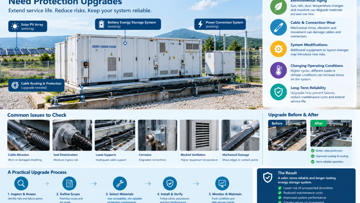
Energy storage projects are designed to operate for years, but their installation environments rarely remain unchanged throughout the system’s service life. Outdoor exposure, temperature cycling, vibration, dust, moisture, mechanical contact, and repeated maintenance activities can gradually affect cables, protective accessories, enclosures, and other supporting components.
For many operating battery energy storage systems (BESS), reliability challenges do not necessarily begin with the battery cells themselves. Some emerge from the surrounding infrastructure: deteriorating cable protection, damaged seals, unsupported cable runs, worn mechanical interfaces, or components that were adequate at commissioning but are no longer suitable for current operating conditions.
This is why existing energy storage projects may need protection upgrades even when their primary equipment remains operational.
A protection upgrade does not always require replacing the battery system or redesigning the entire installation. In some cases, a targeted retrofit involving cable routing, mechanical protection, environmental sealing, identification, and maintenance accessibility can address specific risks more efficiently.
However, every upgrade should begin with an assessment of the actual failure mechanism. Protective accessories cannot compensate for incorrect electrical design, inadequate circuit protection, battery thermal-management deficiencies, or other fundamental engineering problems.
This article explains why existing energy storage projects need protection upgrades, which areas deserve attention, and how operators can plan practical improvements while minimizing unnecessary downtime.
1. Why Protection Requirements Change Over Time
An energy storage installation is designed around a particular set of conditions at the time of commissioning. Over time, equipment use, environmental exposure, maintenance activities, and operational requirements may change.
Several factors can make the original protection arrangement insufficient.
1.1 Environmental Aging
Outdoor energy storage systems may experience continuous exposure to sunlight, rain, humidity, dust, temperature fluctuations, and airborne contaminants.
Depending on the materials and installation conditions, these factors can contribute to cracking, loss of flexibility, corrosion, seal deterioration, or reduced mechanical performance.
Cable sleeves, conduit, glands, seals, and other accessories should therefore be assessed according to their actual condition and suitability for the environment.
A component that appears intact may still require closer inspection if it has exceeded its expected service life or has been exposed to conditions outside its original specification.
1.2 Changes in Cable Routing and Equipment Layout
During the operating life of a project, additional sensors, communication devices, auxiliary equipment, or replacement components may be installed.
These changes can introduce new cable routes, tighter bends, additional penetrations, or greater mechanical stress.
Without a coordinated review, modifications may leave cables unsupported, create contact with sharp edges, obstruct access, or compromise the original separation and protection arrangements.
1.3 Repeated Maintenance and Component Replacement
Maintenance work can involve opening enclosures, disconnecting cables, replacing components, and moving equipment.
Repeated handling may disturb cable supports, protective sleeves, glands, or strain-relief arrangements. Replacement components may also have different dimensions or routing requirements from the original equipment.
A protection review after significant maintenance or modification helps ensure that the installation remains suitable for its current configuration.
1.4 New Operating Requirements
An energy storage project may begin performing more frequent charge and discharge cycles, supporting new loads, or operating under different ambient conditions.
Changes in duty cycle and operating conditions can affect thermal exposure, cable movement, maintenance frequency, and the demands placed on supporting infrastructure.
Any material change in operating conditions should trigger a review of the relevant equipment specifications and protection requirements.
2. Common Warning Signs That an Existing Project Needs an Upgrade
Protection upgrades should be based on observed conditions, inspection findings, or documented changes in risk—not simply on the age of the installation.
The following signs may indicate that further assessment is needed.
| Warning sign | Potential concern | Recommended response |
|---|---|---|
| Cracked, brittle, or deformed cable sleeves | Protective material may no longer provide its intended mechanical protection | Inspect the affected route and replace unsuitable accessories |
| Exposed or damaged cable sheathing | Insulation or mechanical integrity may be compromised | Follow the approved isolation and electrical assessment procedure |
| Loose cable supports or excessive cable movement | Repeated mechanical stress may damage cables or connections | Review routing, supports, and strain relief |
| Deteriorated enclosure seals or cable glands | Environmental protection may be reduced | Verify enclosure and entry-system suitability and restore the specified protection |
| Corrosion around connections or supports | Moisture or environmental exposure may be contributing to deterioration | Assess the cause and follow qualified inspection and repair procedures |
| Restricted ventilation or blocked airflow | Equipment may exceed its permitted operating temperature | Restore required clearances and investigate the thermal conditions |
| Frequent alarms or unexplained temperature changes | An equipment or installation fault may be developing | Investigate using monitoring data and manufacturer procedures |
| New cables added without a routing review | Existing protection and separation arrangements may no longer be adequate | Review the modified installation and update documentation |
These observations do not automatically prove that a major fault exists. They identify conditions that warrant an appropriate assessment.
Where electrical insulation is damaged, overheating is suspected, or moisture has entered electrical equipment, the issue should be escalated promptly and handled by qualified personnel under the site’s safety procedures.
3. Why Cable Protection Is a Priority in Existing BESS Projects
Cable systems connect battery racks, power conversion equipment, distribution equipment, auxiliary systems, monitoring devices, and external electrical infrastructure.
The precise arrangement depends on the system architecture, but cable integrity is important throughout the installation.
3.1 Mechanical Abrasion
Cables may rub against structural members, enclosure edges, cable trays, or neighboring equipment. Vibration and repeated movement can accelerate wear at contact points.
Suitable conduit, protective sleeves, edge protection, clamps, and cable supports can reduce defined mechanical risks when correctly selected and installed.
The upgrade should address the cause of movement or contact, rather than simply covering a damaged section without further investigation.
3.2 Bending and Strain at Connections
Cables that are tightly bent, poorly supported, or placed under tension may impose additional stress on terminals and connectors.
A retrofit should verify the required bend radius, support spacing, connector loading limits, and strain-relief arrangements.
If a cable or connector has already been damaged, adding an external sleeve does not restore its electrical integrity.
3.3 UV and Outdoor Exposure
Outdoor cable routes may require materials specifically rated for sunlight, temperature, moisture, and other environmental conditions.
During a protection upgrade, the team should verify the ratings of existing accessories and identify any components that are unsuitable for the actual exposure.
Product selection should be based on documented specifications, not appearance or general claims that a material is weather-resistant.
3.4 Dust, Moisture, and Contamination
Dust and moisture can affect different parts of an installation in different ways. The level of risk depends on the enclosure design, the electrical equipment, the surrounding environment, and the applicable protection requirements.
Cable glands, enclosure seals, conduits, and protective routing components should work together as part of the installation design.
Adding a sleeve around a cable does not automatically make an electrical connection watertight, dust-tight, or suitable for hazardous environments.
3.5 Cable Identification and Maintenance Access
Older projects may have incomplete cable identification, inaccessible routing, or insufficient documentation of later modifications.
Improving cable labels, route organization, and maintenance access can reduce inspection time and help technicians identify the correct circuit during future work.
These improvements should preserve required separation, clearances, and safe access to electrical equipment.
4. Protection Upgrades Beyond Cable Sleeves
Although cable protection is an important retrofit opportunity, a complete assessment should consider other supporting infrastructure.
Enclosure and Entry Protection
Inspect enclosure doors, gaskets, glands, penetrations, and sealing arrangements for damage, looseness, or incompatibility with current site conditions.
The required enclosure rating must be maintained in accordance with the equipment design and applicable requirements.
Mechanical Supports and Mounting
Check cable trays, brackets, clamps, supports, and mounting hardware for corrosion, deformation, looseness, or other signs of deterioration.
Repairs should restore the intended mechanical support and maintain safe clearances.
Thermal Management
Inspect ventilation paths, filters where fitted, heat exchangers, fans, and other manufacturer-specified thermal-management components.
A protection upgrade must not obstruct airflow, trap unwanted heat, or interfere with temperature monitoring.
Battery and power-conversion equipment should remain within their specified operating conditions.
Corrosion Protection
In coastal, humid, or chemically aggressive environments, metal supports, fasteners, and enclosures may require more frequent inspection.
Any corrosion-control measures should be compatible with the base materials, electrical requirements, and site environment. Coatings and protective wraps should not conceal defects that need to remain inspectable.
Monitoring and Maintenance Documentation
Where the installed system supports relevant monitoring, operators should review alarms, temperature trends, operating history, and fault records as part of the upgrade assessment.
The project documentation should also record replaced accessories, modified cable routes, inspection findings, and any changes to maintenance procedures.
5. Retrofit or Replace? Choosing the Right Upgrade Strategy
Not every existing energy storage project needs the same scope of work. A practical decision process separates localized deterioration from more fundamental technical problems.
Option 1: Targeted Protection Retrofit
A targeted retrofit may be appropriate when the primary electrical equipment remains suitable and the identified issues are limited to replaceable accessories or localized installation deficiencies.
Typical work may include:
- Replacing deteriorated cable sleeves or conduit
- Adding suitable edge protection at cable penetrations
- Improving cable support and strain relief
- Replacing damaged or unsuitable glands and seals
- Reorganizing cable routes where feasible
- Improving identification and inspection access
The work should be based on an inspection and a documented scope of repair.
Option 2: Broader Electrical and Environmental Remediation
A wider upgrade may be necessary when inspections reveal repeated cable damage, unsuitable environmental ratings, significant corrosion, inadequate installation clearances, or deficiencies in electrical protection.
This may require engineering review, circuit isolation, component replacement, updated drawings, and additional commissioning tests.
Protective accessories alone cannot correct deficiencies in conductor sizing, circuit protection, grounding, equipment ratings, or the electrical design.
Option 3: Major Equipment Replacement or System Redesign
More extensive intervention may be required when core equipment is damaged, no longer supported, incompatible with current operating conditions, or unable to meet applicable safety and performance requirements.
Such decisions require qualified technical assessment and should not be reduced to an accessory-replacement exercise.
The guiding principle is simple: use the smallest upgrade scope that adequately addresses the verified risk, but do not use a limited retrofit to conceal a fundamental engineering problem.
6. A Practical Example: Upgrading an Existing Outdoor Storage Installation
Consider an illustrative commercial battery storage installation that has operated outdoors for several years.
During a routine inspection, the maintenance team observes deterioration in selected protective sleeves, unsupported cable sections near equipment entries, and signs that some sealing components require closer examination.
The system has also undergone minor equipment modifications since commissioning.
Instead of immediately replacing the entire storage system, the operator initiates a structured assessment.
Step 1: Identify affected areas.
The team maps the damaged or suspect cable routes and records the relevant environmental exposure and equipment interfaces.
Step 2: Assess electrical safety.
Qualified personnel determine whether any cable, connector, or electrical component has been compromised. Suspected electrical damage is handled according to approved isolation and repair procedures.
Step 3: Identify the underlying causes.
The team checks whether abrasion is caused by poor routing, inadequate support, vibration, or contact with structural edges. It also assesses whether the existing accessories are suitable for the environmental conditions.
Step 4: Select compatible replacements.
Replacement sleeves, supports, glands, seals, and other accessories are selected according to cable dimensions, temperature, environmental exposure, mechanical requirements, and applicable specifications.
Step 5: Complete and document the retrofit.
The team performs the required checks, records modifications, updates relevant drawings, and confirms that the installation meets the applicable acceptance criteria before returning equipment to normal service.
Step 6: Review the results over time.
Subsequent inspections assess whether the identified issues recur and whether the revised routing and protection arrangements remain effective.
This example illustrates a retrofit method. It does not establish that a specific percentage of failures or maintenance costs will be avoided.
7. How to Plan a Protection Upgrade With Minimal Downtime
For an operating energy storage project, the upgrade plan should balance technical requirements with operational continuity.
Phase 1: Review Existing Information
Collect available electrical drawings, equipment manuals, commissioning records, maintenance logs, previous modification records, and environmental specifications.
Identify any gaps between the documented installation and the current configuration.
Phase 2: Perform a Site Inspection
Inspect accessible cable routes, protective accessories, equipment entries, mounting supports, enclosures, and ventilation paths.
Use qualified personnel and the site’s established safety procedures for any inspection involving electrical hazards.
Phase 3: Prioritize Risks
Rank findings according to safety implications, potential consequence, likelihood of deterioration, and operational impact.
Immediate safety concerns should take priority over cosmetic improvements or general upgrades.
Phase 4: Prepare a Retrofit Bill of Materials
Specify the required products and components based on actual dimensions and conditions.
Confirm compatibility with the existing cable types, installation methods, temperature range, environmental exposure, and required ratings.
For critical equipment, use manufacturer-approved parts or obtain technical confirmation where required.
Phase 5: Coordinate Work and Isolation
Plan the required shutdown, isolation, access, and testing activities with the site’s operating team.
Do not assume that cable accessories can be replaced safely while a circuit remains energized. Work methods must follow applicable safety rules and equipment-specific procedures.
Phase 6: Verify and Document
After installation, complete the required inspections and tests. Confirm that electrical protection, cable support, sealing, clearances, and thermal-management requirements remain satisfied.
Update drawings, inspection records, and maintenance instructions so that future work reflects the actual installation.
8. Evaluating the Business Case for Protection Upgrades
Protection upgrades should be evaluated against the cost and consequences of leaving identified risks unresolved.
A useful assessment considers:
- Cost of replacement accessories and installation labor
- Planned shutdown and access costs
- Potential cost of unplanned maintenance
- Operational consequences of a component failure
- Inspection and replacement frequency
- Expected service life of the replacement components
- Compatibility with existing equipment
- Requirements for testing, documentation, and compliance
A targeted retrofit may be economically attractive when a relatively small intervention addresses a clear and recurring problem. However, the financial benefit depends on the actual installation and risk profile.
Operators should avoid promising a universal reduction in downtime or maintenance costs without supporting project data.
A protection upgrade is best justified by a documented risk assessment, a clear scope of work, and measurable acceptance criteria.
9. Common Mistakes During Energy Storage Protection Upgrades
Replacing Accessories Without Investigating the Cause
A new sleeve may deteriorate again if the underlying cable movement, sharp-edge contact, or excessive bending remains unresolved.
Assuming External Protection Restores Damaged Electrical Components
Protective covers cannot restore damaged insulation, repair a defective connector, or correct an undersized conductor.
Selecting Materials Based on Price Alone
Low initial cost does not guarantee suitability for UV exposure, high temperatures, chemical contact, vibration, or long-term mechanical stress.
Blocking Ventilation or Inspection Access
An upgrade that obstructs airflow, hides critical components, or makes future inspection difficult may introduce new problems.
Ignoring Documentation
Unrecorded changes make later troubleshooting, maintenance, and compliance verification more difficult.
Applying the Same Upgrade to Every Site
A coastal installation, an indoor industrial facility, and a dusty outdoor site may require different materials and inspection priorities. The upgrade must reflect the actual operating environment.
10. A Protection Upgrade Checklist for Existing BESS Projects
Before approving a retrofit, operators can use the following checklist as a starting point.
- Review the current equipment configuration and historical maintenance records.
- Inspect cable routes for abrasion, excessive bending, unsupported spans, and mechanical contact.
- Check sleeves, conduits, glands, seals, and supports for deterioration.
- Verify suitability for UV exposure, moisture, dust, temperature, and other site conditions.
- Assess enclosure integrity and cable-entry protection.
- Confirm that thermal-management paths and service clearances remain unobstructed.
- Investigate any electrical damage, corrosion, overheating, or repeated alarms.
- Confirm replacement component compatibility and required ratings.
- Plan isolation, qualified installation, and required verification tests.
- Update drawings, maintenance records, and inspection schedules.
- Establish follow-up checks to evaluate the effectiveness of the upgrade.
This checklist is a planning aid and does not replace the site’s formal risk assessment, applicable standards, manufacturer requirements, or qualified engineering review.
Frequently Asked Questions
Why do existing energy storage systems need protection upgrades?
Environmental aging, cable movement, maintenance activities, equipment modifications, and changing operating conditions can reduce the suitability of the original protection arrangements. An inspection can identify whether targeted upgrades are necessary.
Do protection upgrades require replacing the battery system?
Not necessarily. If the battery and other primary equipment remain suitable, a targeted retrofit of cable protection, supports, glands, seals, or other accessories may address specific risks. Major equipment problems require a broader technical assessment.
Which components are commonly reviewed during a protection upgrade?
Common inspection areas include cable sleeves, conduit, cable supports, strain relief, enclosure entries, glands, seals, mounting hardware, ventilation paths, and relevant monitoring records.
Can cable sleeves prevent all cable-related failures?
No. Suitable sleeves can reduce certain forms of mechanical or environmental damage, but they cannot correct improper cable sizing, defective electrical connections, inadequate circuit protection, or damage that has already compromised cable integrity.
When should an energy storage protection upgrade be performed?
An upgrade should be considered when inspections reveal deterioration, after significant equipment modifications, when operating conditions change, or when repeated maintenance findings indicate a persistent installation problem. Inspection frequency should follow the applicable maintenance plan and risk assessment.
How can operators reduce downtime during a retrofit?
They can prepare accurate drawings, inspect and prioritize the work in advance, confirm component compatibility, coordinate approved isolation procedures, stage materials, and define acceptance criteria before work begins.
What should be considered when selecting replacement protection accessories?
Key factors include cable dimensions, mechanical exposure, temperature, UV and weather resistance where applicable, chemical compatibility, installation method, maintenance access, and the required technical ratings.
Existing energy storage projects can develop protection needs long after their original commissioning. Environmental exposure, cable movement, equipment modifications, and routine maintenance can gradually change the conditions under which the system operates.
A structured protection upgrade helps operators identify deteriorating components, address specific risks, and improve the maintainability of existing installations without automatically replacing the entire system.
The most effective approach begins with inspection, investigates the underlying cause, selects technically compatible components, and verifies the completed work. Cable protection, routing accessories, sealing components, and mechanical supports can all contribute to reliability when they are selected and installed for the actual application.
GR-NEWenergy focuses on energy storage integration and O&M-related solutions, including cable protection, installation accessories, and practical protection measures for industrial and energy infrastructure. For existing projects, these solutions can support targeted retrofit work as part of a broader, properly engineered protection and maintenance strategy.
- Why do existing energy storage projects need protection upgrades? Environmental aging, cable movement, equipment modifications, and changing operating conditions can make original protection arrangements unsuitable over time.
- Can an existing BESS be upgraded without replacing the batteries? Yes, when the identified issues are limited to suitable retrofit components and the primary equipment remains technically acceptable.
- Which protection components should be inspected in an existing BESS? Cable sleeves, conduit, supports, glands, seals, enclosure entries, mounting hardware, and ventilation paths are common inspection areas.
- Do cable protection accessories eliminate electrical risks? No. They address specific mechanical or environmental risks and cannot replace correct electrical design, circuit protection, or repair of damaged components.
- How should operators plan an energy storage retrofit? Review records, inspect the installation, prioritize risks, select compatible components, coordinate safe isolation, verify completed work, and update maintenance documentation.