
Low-voltage photovoltaic (PV) and battery energy storage systems are increasingly used in residential, commercial, and small industrial applications. These systems can help users increase solar self-consumption, reduce electricity costs, and improve energy flexibility.
However, reliable operation depends on more than the quality of individual batteries or inverters. Electrical connections, battery management, module compatibility, thermal conditions, installation quality, and maintenance practices all influence long-term system performance.
In low-voltage PV + storage systems, these details are particularly important because high current can flow through battery cables and electrical connections even when the system voltage is relatively low. Poor connections, inadequate cable sizing, or unsuitable protective components can lead to excessive voltage drop, overheating, equipment faults, and unnecessary downtime.
This article explains the main reliability challenges in low-voltage PV + storage modules and outlines practical measures for installers, system integrators, and maintenance teams.
1. Understanding Reliability in Low-Voltage PV + Storage Systems
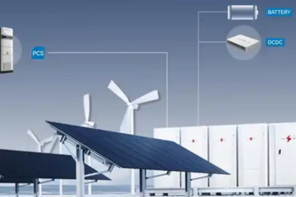
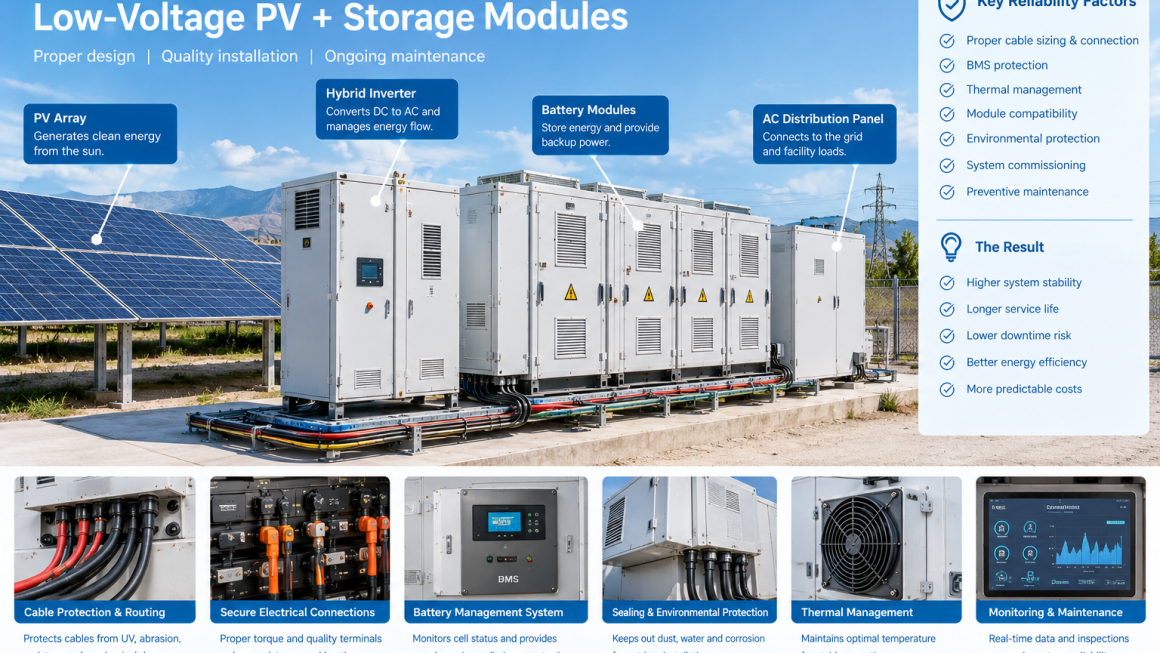
A low-voltage PV + storage system typically combines PV modules, an inverter or hybrid inverter, a battery pack, a battery management system (BMS), electrical protection devices, and monitoring equipment.
The exact architecture varies by application. Some systems use low-voltage batteries connected to hybrid inverters, while others use separate PV and battery conversion equipment.
Regardless of the configuration, system reliability depends on several interconnected factors:
- Electrical reliability: Stable connections, appropriate conductor sizing, and correctly coordinated protection.
- Battery reliability: Suitable operating limits, cell monitoring, and effective battery management.
- Thermal reliability: Maintaining batteries, cables, and power electronics within their specified temperature ranges.
- Control reliability: Accurate monitoring, compatible communication, and correct charging and discharging logic.
- Environmental reliability: Protection against dust, moisture, UV exposure, corrosion, and mechanical damage.
- Maintenance reliability: Accessible components, documented inspections, and timely fault response.
A system can contain high-quality components and still perform poorly if these elements are not properly integrated.
2. Managing High Current in Low-Voltage Battery Systems
One of the most important electrical considerations is the relationship between voltage and current.
For a given power level, a lower DC voltage generally requires a higher current.
For example, consider a battery system delivering 5 kW of DC power. Ignoring conversion losses:
At 48 V:
5,000 W ÷ 48 V ≈ 104 A
At 400 V:
5,000 W ÷ 400 V = 12.5 A
The 48 V system requires substantially more current to deliver the same power.
This difference affects conductor sizing, terminal selection, connector ratings, fuse selection, and the management of electrical losses.
Why high current matters
Cable resistance causes power loss and voltage drop. The simplified relationship is:
Power loss = Current² × Resistance
As current increases, resistive losses can rise significantly if conductor resistance remains unchanged.
Loose terminals, undersized conductors, damaged connectors, and poor crimping can introduce additional resistance at localized points. These locations may become hot during charging or discharging.
Practical solutions
- Size battery cables according to current, cable length, installation conditions, insulation temperature rating, and applicable electrical requirements.
- Use connectors and terminals rated for the intended current and conductor type.
- Follow manufacturer specifications for crimping, terminal preparation, and tightening torque.
- Keep cable runs as short as reasonably practical without compromising installation safety or service access.
- Inspect for discoloration, damaged insulation, corrosion, or signs of overheating.
- Verify voltage drop and connection performance during commissioning where appropriate.
Cable sizing should not be based on current alone. Ambient temperature, cable grouping, installation method, allowable voltage drop, and local regulations must also be considered.
3. Battery Management System: The Foundation of Battery Protection
The battery management system plays a central role in the safe operation of a battery module.
Depending on the battery architecture, the BMS monitors cell or module voltages, current, temperature, and state of charge. It may also estimate state of health and communicate operating limits to the inverter or energy management system.
When an operating parameter approaches or exceeds a permitted limit, the BMS may restrict charging or discharging, issue an alarm, or initiate a protective shutdown.
Key BMS functions
Overcharge protection
The BMS monitors battery voltage and charging conditions to help prevent charging beyond the permitted operating range.
Over-discharge protection
The BMS can limit or stop discharge when the battery reaches its configured lower operating boundary.
Overcurrent protection
The system monitors current and responds to conditions outside its specified operating limits.
Temperature monitoring
Temperature measurements help the system manage charging, discharging, and protective responses under hot or cold conditions.
Communication with the inverter
A compatible BMS can provide battery status and operating limits to the inverter, enabling coordinated control.
Practical reliability measures
Installers should verify the battery and inverter communication settings, confirm the required BMS firmware and protocol, and test the relevant alarms before handover.
The BMS should not be treated as a substitute for correctly rated fuses, disconnect devices, wiring, or other required electrical protection. These elements serve complementary purposes and must be coordinated within the system design.
4. Module Compatibility and Parallel Battery Connections
Some low-voltage storage systems use multiple battery modules connected in parallel to increase available capacity or current capability.
Parallel configurations can improve scalability, but they introduce additional engineering requirements.
Battery modules may differ in state of charge, internal resistance, temperature, age, or operating history. These differences can affect current sharing and cause some modules to experience greater electrical or thermal stress than others.
Common challenges
- Connecting modules that are not approved for parallel operation
- Combining incompatible battery models or capacities
- Connecting modules with substantially different states of charge
- Unequal cable lengths or connection resistance
- Exceeding inverter or BMS current limits
- Expanding a system without confirming compatibility with existing modules
Practical solutions
Use only battery combinations explicitly supported by the manufacturer. Follow the specified module matching, pre-connection charging, wiring, communication, and configuration procedures.
Where the design permits parallel connections, use an approved busbar or distribution arrangement and follow the manufacturer’s cable-sizing and connection requirements.
After installation, verify module communication, total current, individual module status where available, and the behavior of the system under representative operating conditions.
Important: More battery modules do not automatically mean better reliability. The parallel configuration must be designed to ensure compatible operation, appropriate current sharing, and effective fault protection.
5. Thermal Management and Operating Temperature
Temperature affects battery performance, charging capability, degradation, and safety. It also affects the performance of cables, connectors, inverters, and other electrical components.
Low-voltage systems installed in garages, utility rooms, outdoor enclosures, or industrial environments may encounter significant temperature variation.
High temperatures can accelerate battery aging and increase cooling requirements. Low temperatures can restrict charging or reduce available battery power, depending on the chemistry and manufacturer’s operating limits.
Practical solutions
- Install the battery within its specified operating temperature range.
- Avoid direct solar heating and locations where hot exhaust air accumulates.
- Maintain the required ventilation and equipment clearances.
- Keep cooling openings unobstructed.
- Monitor battery and inverter temperature alarms.
- Follow the manufacturer’s restrictions for charging at low temperatures.
- Review temperature trends during seasonal maintenance.
Thermal protection should address the whole installation, not only the battery enclosure. High-resistance electrical connections can generate localized heat even when the surrounding room temperature is acceptable.
6. Protecting Cables, Connectors, and Electrical Interfaces
Battery and PV cables often pass through confined spaces, cable trays, enclosure openings, and outdoor routing sections.
These locations may expose cables to abrasion, compression, vibration, UV radiation, dust, moisture, or accidental contact during maintenance.
In low-voltage battery systems, poor cable connections deserve particular attention because high current can magnify the consequences of additional electrical resistance.
Recommended protection measures
Cable routing and restraint
Secure cables to prevent excessive movement, bending, tension, and contact with sharp edges. Maintain the required bend radius and strain relief.
Mechanical protection
Use suitable protective sleeves, conduits, cable trays, or edge guards where mechanical damage is foreseeable.
Environmental protection
Choose UV-resistant and moisture-resistant routing accessories for outdoor sections where required. Use compatible cable glands and seals at enclosure entries.
Connector integrity
Use approved connectors and compatible mating components. Check for contamination, damaged contacts, loose fittings, or signs of corrosion.
Service access
Arrange cables so that technicians can inspect and replace components without placing unnecessary stress on neighboring connections.
Protection products should be selected according to the specific hazard. An abrasion-resistant sleeve, for example, should not be assumed to provide electrical insulation, waterproofing, or fire resistance unless those properties are documented for that product and installation.
7. Voltage Drop and System Efficiency
Voltage drop is another important factor in low-voltage PV + storage installations.
When current flows through a conductor, its resistance causes the voltage at the load to differ from the voltage at the source. Excessive voltage drop can reduce efficiency, affect equipment operation, and complicate system control.
The effect becomes more significant with higher current, longer cable runs, or inadequate conductor cross-sectional area.
Practical solutions
- Calculate voltage drop using the expected operating current and cable length.
- Consider the complete current path, including positive and negative conductors.
- Use appropriate conductor cross-sectional areas.
- Minimize unnecessary cable length.
- Check connections and terminal resistance.
- Measure operating voltage at suitable points during commissioning.
The acceptable voltage drop depends on the equipment specifications, circuit design, and applicable electrical standards. Installers should follow the relevant project requirements rather than apply a single universal percentage to every circuit.
8. Inverter Compatibility and Charging Control
A battery may be electrically connected to an inverter without being fully compatible with its control system.
Battery voltage ranges, charging current limits, discharge limits, communication protocols, and configuration parameters must match the intended operating arrangement.
Incorrect settings can cause unexpected shutdowns, restricted charging, inaccurate state-of-charge readings, or repeated communication alarms.
Practical solutions
Before commissioning, confirm:
- The battery model is approved for the selected inverter.
- The supported voltage range matches the battery configuration.
- Charging and discharging current limits are correctly configured.
- The required communication protocol and wiring are correct.
- The BMS and inverter firmware versions are compatible.
- The system’s operating modes match the project requirements.
- Protective shutdown and recovery behavior are understood.
After configuration, test charging and discharging under controlled conditions and review system logs for alarms or abnormal behavior.
Avoid changing battery protection limits beyond manufacturer-approved settings simply to increase available power or energy.
9. Commissioning: Verify the Complete System
A structured commissioning process helps identify installation defects before the system enters routine operation.
Testing should cover more than whether the inverter powers on or the battery begins charging.
Recommended commissioning checklist
| Inspection area | What to verify |
|---|---|
| Physical installation | Mounting, clearances, enclosure condition, cable routing |
| Electrical connections | Correct polarity, conductor sizing, terminal condition, specified torque |
| Protection | Required fuses, disconnects, grounding, and protective coordination |
| Battery configuration | Module compatibility, approved capacity configuration, BMS settings |
| Communication | Inverter-BMS communication and relevant monitoring signals |
| Charging and discharging | Operation within specified voltage, current, and temperature limits |
| Alarms | Correct reporting and protective response according to the design |
| Documentation | Test records, equipment settings, wiring diagrams, and maintenance instructions |
Electrical testing and energization must be performed by qualified personnel following manufacturer procedures and applicable regulations.
The commissioning record should establish the initial operating condition of the system. This provides a useful reference when troubleshooting future performance changes.
10. Preventive Maintenance for Long-Term Reliability
Reliability is not achieved once and then permanently guaranteed. Battery systems and their supporting electrical components require ongoing monitoring and maintenance.
A preventive maintenance program can help identify developing problems before they lead to unplanned downtime.
Recommended maintenance activities
Review operating data
Check battery temperature, charge and discharge behavior, alarm history, and available state-of-health indicators.
Inspect electrical interfaces
Look for visible cable damage, loose fittings, corrosion, discoloration, or signs of overheating. Any torque checks should follow the manufacturer’s safe maintenance procedure.
Inspect environmental protection
Check enclosure seals, cable glands, protective sleeves, and routing components for damage or deterioration.
Check thermal management
Inspect cooling openings, filters, fans, or other thermal management components according to the maintenance instructions.
Review system configuration
Confirm that monitoring, communication, and control settings remain appropriate after firmware updates or equipment changes.
Maintain service records
Record inspections, faults, corrective actions, replaced components, and significant changes in system performance.
Maintenance frequency should be based on manufacturer recommendations, operating conditions, usage patterns, and applicable regulations. Systems exposed to high temperatures, dust, humidity, or corrosive environments may require more frequent inspection.
11. Common Reliability Mistakes to Avoid
Mistake 1: Treating low voltage as low risk
Low voltage does not eliminate the risks associated with high current. Short circuits can produce substantial fault currents, so suitable conductors, protection devices, and safe working procedures remain essential.
Mistake 2: Using undersized battery cables
Inadequate conductors can increase voltage drop, energy losses, and thermal stress. Cable selection should account for the actual installation conditions.
Mistake 3: Mixing incompatible battery modules
Unapproved module combinations can introduce current-sharing, communication, and protection problems.
Mistake 4: Relying entirely on the BMS
The BMS is one layer of protection. It does not replace correctly designed electrical protection, sound installation practices, or regular inspection.
Mistake 5: Ignoring small signs of overheating
Discoloration, damaged insulation, unusual connector temperatures, and repeated alarms may indicate developing faults that require investigation.
Mistake 6: Overlooking cable protection and sealing
Poorly protected cables and enclosure entries can deteriorate under environmental exposure and make maintenance more difficult.
Mistake 7: Skipping system-level commissioning
A successful startup does not necessarily confirm correct operation across all required charging, discharging, monitoring, and protection functions.
12. A Practical Reliability Checklist for Installers
Before handing over a low-voltage PV + storage system, installers should confirm that the following areas have been addressed.
- Battery and inverter compatibility verified
- Approved battery module configuration confirmed
- Cable sizing and voltage drop evaluated
- Connectors and terminals installed according to manufacturer requirements
- Required electrical protection and grounding completed
- Battery and inverter temperature limits confirmed
- BMS communication and alarms tested
- Cable routing and environmental protection inspected
- Charging and discharging functions verified
- Monitoring and control settings documented
- Maintenance access and inspection procedures established
- Commissioning records and handover documents completed
This checklist should be adapted to the battery chemistry, system architecture, installation environment, and local electrical requirements.
Reliability Comes from the Entire Installation
Ensuring reliability in low-voltage PV + storage modules requires coordinated attention to electrical design, battery management, module compatibility, thermal conditions, cable protection, commissioning, and maintenance.
The relatively low voltage of these systems does not remove the importance of current management, connection quality, or fault protection. In many applications, high current makes conductor sizing and terminal integrity especially important.
For installers and system integrators, the most effective approach is to verify compatibility before procurement, follow approved installation procedures, test the complete system before handover, and maintain a documented inspection program.
Attention to cable routing, connector condition, environmental sealing, and service access can further support long-term reliability, particularly where equipment operates in hot, dusty, humid, or outdoor environments.
A reliable low-voltage PV + storage system is not defined by battery quality alone. It is the result of compatible components, sound electrical engineering, disciplined installation, effective protection, and consistent maintenance.