Integrating photovoltaic (PV) systems with battery energy storage can help commercial and industrial facilities improve solar energy utilization, manage electricity costs, and increase energy flexibility. However, a successful PV + storage project requires more than installing solar panels and connecting a battery system.
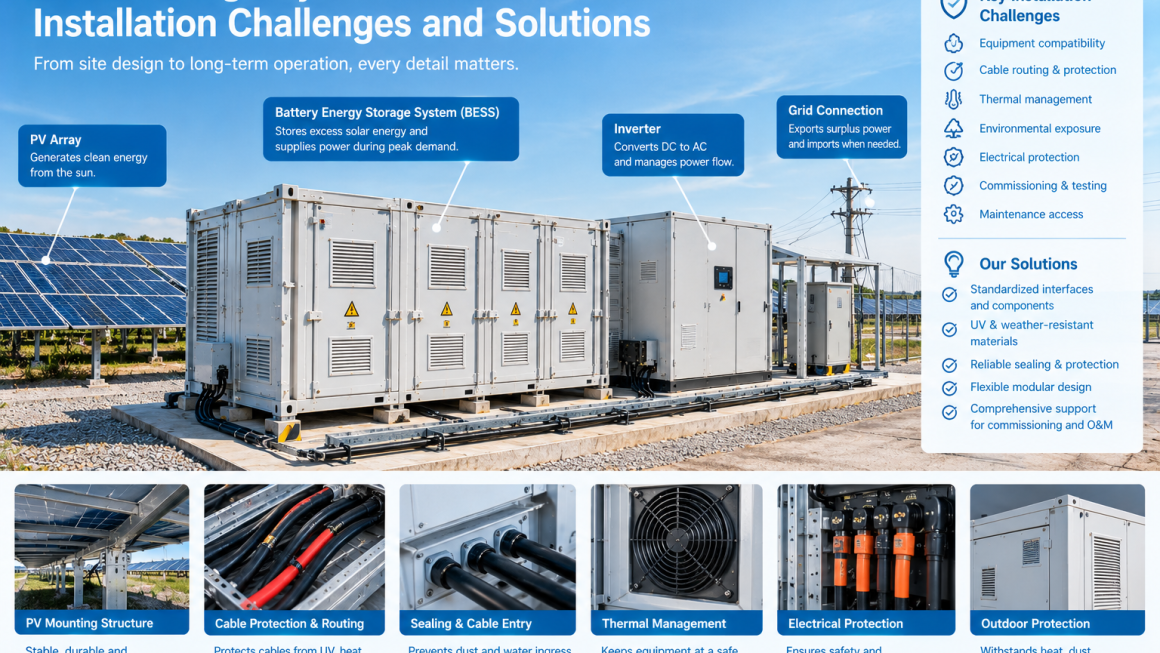
Installation teams must coordinate electrical equipment, battery systems, inverters, protection devices, monitoring platforms, and site infrastructure. They must also address practical challenges such as limited installation space, cable routing, equipment compatibility, environmental exposure, commissioning, and long-term maintenance.
Even when all major components meet their individual specifications, installation problems can still affect system performance, reliability, and operating costs.
This article examines the most common PV + storage system installation challenges and presents practical solutions for installers, EPC contractors, system integrators, and facility operators.
1. Equipment Compatibility and System Integration
One of the first challenges in a PV + storage project is ensuring that all major components can operate together as a coordinated system.
A typical installation may include:
- PV modules and mounting structures
- String or hybrid inverters
- Battery energy storage systems
- Battery management systems (BMS)
- Energy management systems (EMS)
- AC and DC protection devices
- Metering, monitoring, and communication equipment
These components may come from different manufacturers. Their electrical ratings, communication protocols, operating limits, and control logic must be compatible with the intended system architecture.
For example, a battery may have sufficient nominal capacity for a project, but the selected inverter may not support its voltage range, charging requirements, or communication interface.
Similarly, a monitoring platform may display inverter output without providing the battery status or control functions required for coordinated operation.
Practical solutions
Confirm compatibility before procurement. Review the inverter manufacturer’s approved battery list, battery voltage range, charging and discharging limits, and supported communication protocols.
Define the system architecture early. Establish whether the project will use a DC-coupled or AC-coupled configuration, and identify how the PV system, battery, grid connection, and loads will interact.
Assign responsibility for integration. Clarify who is responsible for inverter configuration, BMS communication, EMS programming, and system-level commissioning.
Test communication before final handover. Verify that the relevant devices exchange the required data and that alarms and control commands function correctly.
A component compatibility checklist can reduce commissioning delays and help prevent expensive equipment changes after delivery.
2. Choosing Between AC-Coupled and DC-Coupled Systems
The choice between AC coupling and DC coupling affects system architecture, installation complexity, conversion losses, and retrofit flexibility.
In a DC-coupled system, PV generation and battery storage connect through a shared DC-side architecture, often using a hybrid inverter. In an AC-coupled system, the PV inverter and battery inverter typically connect separately on the AC side.
Neither configuration is universally superior.
DC coupling may be attractive for new installations that can be designed around a compatible hybrid inverter. AC coupling may be suitable when adding storage to an existing PV installation, particularly when retaining the existing PV inverter is desirable.
Practical solutions
- Evaluate the existing electrical infrastructure before selecting the configuration.
- Compare conversion pathways, system efficiency, and expected operating modes.
- Check whether the system must support backup power or islanded operation.
- Confirm the inverter’s power limits and the permitted PV and battery operating ranges.
- Consider future expansion and maintenance requirements.
For retrofit projects, preserving existing equipment can reduce replacement work, but compatibility and system control still require careful verification.
3. Cable Routing and Electrical Connection Challenges
Cable routing is one of the most underestimated aspects of PV + storage installation.
A project may require DC cables from PV strings, battery power cables, AC connections, communication cables, grounding conductors, and auxiliary power wiring. Poor routing can create installation congestion, complicate maintenance, and expose cables to mechanical damage.
Outdoor cables may also be exposed to sunlight, rain, dust, temperature changes, abrasion, or chemical contamination.
In industrial and utility-scale environments, long cable routes and dense equipment layouts can make these problems more difficult to manage.
Practical solutions
Separate and organize cable routes. Follow the applicable electrical code and manufacturer requirements for separating power, communication, and control wiring.
Protect cables against site-specific hazards. Select suitable conduits, cable trays, flexible sleeves, protective braids, or other routing accessories according to the required temperature rating, UV resistance, abrasion resistance, and environmental exposure.
Maintain bend radius and strain relief. Prevent excessive bending, pulling force, and mechanical stress at terminals and cable entries.
Use suitable cable entry and sealing components. Cable glands and sealing accessories should match the cable diameter, enclosure design, and required ingress protection.
Label cables consistently. Clear identification helps technicians isolate circuits, troubleshoot faults, and perform future maintenance.
Cable protection products should be selected according to the actual hazard. A protective sleeve designed for abrasion resistance, for example, should not automatically be treated as fire protection or a waterproof enclosure.
4. Grounding, Electrical Protection, and Safety
PV + storage systems combine multiple electrical sources and operating conditions. Incorrect grounding or poorly coordinated protection devices can create serious safety risks.
The design may need to address PV DC circuits, battery circuits, inverter AC connections, protective earthing, surge protection, overcurrent protection, and isolation.
The required protection depends on the equipment architecture, system voltage, grid connection, installation environment, and applicable local standards.
Practical solutions
- Develop a documented grounding and bonding plan.
- Verify protective device ratings and coordination against the design requirements.
- Install isolation and emergency shutdown provisions where required.
- Check polarity, conductor identification, terminal torque, and cable termination quality.
- Inspect surge protection and lightning protection provisions where applicable.
- Complete required electrical tests before energization.
- Document inspection results and commissioning records.
Installation and testing must be carried out by appropriately qualified personnel under the applicable local electrical and safety requirements.
5. Battery Placement, Ventilation, and Thermal Management
Battery systems can be sensitive to temperature, and their installation environment influences performance, aging, and operating safety.
Outdoor installations may experience direct solar exposure, high ambient temperatures, humidity, dust, and seasonal weather changes. Indoor installations may face restricted ventilation, limited access, or competing space requirements.
Inadequate thermal management can lead to temperature alarms, reduced charging or discharging capability, and accelerated degradation. The consequences depend on the battery chemistry, enclosure design, and operating conditions.
Practical solutions
Follow manufacturer installation clearances. Maintain the required access space around battery cabinets, ventilation openings, and service panels.
Assess the actual site climate. Use expected ambient temperatures, solar exposure, humidity, and dust levels when evaluating enclosure and cooling requirements.
Avoid obstructing airflow. Keep cooling inlets and outlets clear and avoid placing equipment where exhaust air recirculates into the intake.
Monitor temperature and alarms. Confirm that the BMS and thermal management controls report abnormal conditions and respond according to their design.
Plan for inspection and maintenance. Ensure technicians can access filters, cooling equipment, electrical connections, and replaceable components.
The enclosure’s ingress protection rating, cooling capacity, and environmental limits should be selected for the installation site rather than assumed from a generic product description.
6. Weatherproofing and Environmental Protection
Outdoor PV + storage equipment must withstand the environmental conditions expected over its service life.
Potential challenges include:
- UV exposure and heat-related material aging
- Dust and airborne particles
- Rainwater and moisture ingress
- Salt-laden air in coastal locations
- Sand and abrasion in dry environments
- Corrosion at exposed metal components
- Water accumulation around cable entries and equipment bases
These conditions can affect cable insulation, enclosure seals, connectors, mounting hardware, and other installation accessories.
Practical solutions
Match protection to the environment. Evaluate the required UV resistance, corrosion resistance, temperature range, ingress protection, and mechanical durability of each relevant component.
Protect vulnerable cable sections. Use suitable cable sleeves or protective conduits where cables may experience abrasion, sunlight exposure, or accidental impact.
Inspect entry points and seals. Check cable glands, gaskets, enclosure interfaces, and unused openings during installation and periodic maintenance.
Consider corrosion exposure. Select compatible materials and coatings for the local environment, particularly in coastal or chemically aggressive industrial sites.
Avoid trapped water and debris. Ensure the equipment foundation, drainage, and cable routing do not create unnecessary moisture traps.
Protective accessories can reduce specific environmental risks, but they cannot replace correctly rated equipment, proper enclosure design, or the manufacturer’s installation instructions.
7. Communication and Energy Management Configuration
A PV + storage system may require coordinated control of solar generation, battery charging and discharging, grid import and export, and site loads.
Incorrect configuration can prevent the system from operating as intended. For example, a system designed to increase solar self-consumption may export excess energy when the battery should be charging, or a peak-shaving system may discharge at an inappropriate time.
Meter placement, measurement direction, communication failures, and control priority settings can all affect system behavior.
Practical solutions
- Confirm the location and orientation of current transformers or other metering devices.
- Verify that measured import, export, generation, and battery power have the correct sign and magnitude.
- Configure charging and discharging priorities according to the project objectives.
- Test grid-connected and backup operating modes where supported.
- Verify communication-loss behavior and alarm handling.
- Confirm time settings, tariff schedules, and demand thresholds.
- Document the final configuration and password or access-control handover process.
For projects involving demand management, the EMS should use the utility’s relevant demand measurement interval and billing rules rather than rely only on instantaneous readings.
8. Commissioning and Performance Verification
Installation is not complete when the equipment is physically connected. The system must also be tested under its intended operating conditions.
Commissioning problems often arise when responsibilities are unclear, configuration records are incomplete, or individual components are tested without verifying their behavior as a complete system.
Recommended commissioning sequence
Step 1: Physical inspection
Check equipment mounting, clearances, cable routing, labeling, enclosure sealing, and visible installation defects.
Step 2: Electrical verification
Complete the tests required by the system design, equipment manufacturers, and local regulations before energization.
Step 3: Communication verification
Confirm that the inverter, BMS, EMS, meters, and monitoring platform communicate correctly where applicable.
Step 4: Functional testing
Test the required charging, discharging, grid interaction, alarms, and operating modes according to the approved commissioning procedure.
Step 5: Performance review
Compare observed power, energy, temperature, and control behavior with the expected operating parameters.
Step 6: Handover documentation
Provide the owner with the as-built drawings, equipment settings, test records, warranty information, maintenance instructions, and escalation contacts.
Acceptance criteria should be agreed before commissioning begins. This helps distinguish installation defects from configuration issues, grid limitations, and normal equipment operating constraints.
9. Common Installation Mistakes and How to Prevent Them
| Common mistake | Potential consequence | Recommended prevention |
|---|---|---|
| Selecting components without checking compatibility | Integration delays or limited functionality | Confirm ratings, interfaces, and supported configurations before ordering |
| Poor cable organization | Difficult maintenance and increased mechanical risk | Plan cable routes and apply suitable protection and labeling |
| Ignoring site temperature and dust | Thermal alarms or accelerated component aging | Assess environmental conditions during design |
| Incorrect meter configuration | Inaccurate control or energy measurements | Verify meter orientation, measurement values, and communication |
| Incomplete commissioning | Undetected faults or incorrect operating modes | Use a documented system-level commissioning checklist |
| No maintenance access plan | Longer service interruptions | Design for inspection, isolation, and component replacement |
| Assuming all protective sleeves serve the same purpose | Inadequate protection against specific hazards | Match each accessory to the relevant technical requirement |
Preventing these mistakes during design and installation is generally easier than correcting them after the system has entered service.
10. Maintenance Planning Starts During Installation
Maintenance requirements should be considered before equipment is installed, not after the first fault occurs.
A well-planned installation makes it easier to inspect connections, replace worn accessories, identify abnormal temperatures, and troubleshoot communication or control problems.
For commercial and industrial systems, maintenance planning should cover:
- Scheduled inspection of electrical connections and visible cable damage
- Review of battery, inverter, and thermal management alarms
- Inspection of enclosure seals and cable entry points
- Cleaning or replacement of filters according to manufacturer guidance
- Review of monitoring data and system performance trends
- Verification of protective devices according to the maintenance plan
- Replacement planning for components subject to wear or environmental aging
Remote monitoring can reduce the need for some site visits, but it does not eliminate the need for physical inspections and required electrical maintenance.
For systems in dusty, hot, coastal, or other challenging environments, the maintenance schedule should reflect the actual exposure and manufacturer recommendations.
11. A Practical Installation Checklist for PV + Storage Projects
Before installation, project teams should confirm the following items.
System design
- PV and battery system architecture confirmed
- Inverter and battery compatibility verified
- Required charging, discharging, and backup modes defined
- Electrical ratings and protection requirements reviewed
Site preparation
- Installation area, foundation, and service clearances checked
- Environmental conditions assessed
- Cable routes and equipment entry points planned
- Drainage, ventilation, and access requirements addressed
Installation
- Cables routed and protected appropriately
- Cable entries sealed according to design requirements
- Grounding, bonding, and electrical protection completed
- Equipment labels and circuit identification installed
- Installation records maintained
Commissioning and handover
- Electrical tests completed
- Communication and metering verified
- Required operating modes tested
- Alarms and monitoring functions checked
- Documentation and maintenance responsibilities transferred
The exact checklist should be adapted to the system architecture, project scope, and local regulatory requirements.
Reliable PV + Storage Depends on More Than Major Equipment
PV + storage integration presents challenges across electrical design, component compatibility, cable management, thermal control, environmental protection, commissioning, and maintenance.
Many of these challenges can be reduced through early planning, clear integration responsibilities, site-specific equipment selection, and systematic testing.
For installers and system integrators, the objective is not simply to connect PV generation with battery storage. It is to deliver a coordinated system that operates according to the project’s technical and financial requirements and remains maintainable throughout its service life.
Attention to cable routing, sealing, protective accessories, monitoring, and maintenance access can also improve the quality of the installation, especially in industrial environments where equipment is exposed to heat, dust, vibration, or outdoor weather.
A reliable PV + storage installation begins with system-level engineering and continues with disciplined commissioning and long-term maintenance planning.