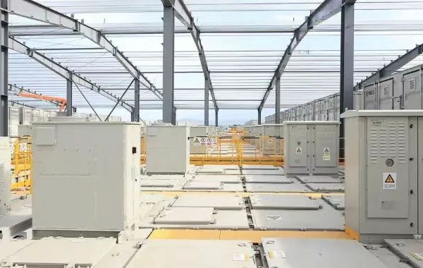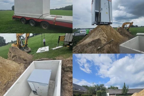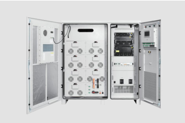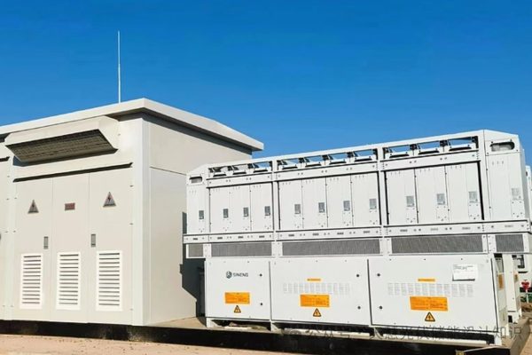
Small-scale photovoltaic (PV) and battery energy storage systems are increasingly used in commercial buildings, workshops, small factories, agricultural facilities, and remote sites. By combining solar generation with battery storage, these systems can improve on-site solar utilization, provide greater control over electricity consumption, and support selected backup-power applications when properly designed.
However, the reliability of a small-scale PV + storage system depends on more than the performance of its solar panels and batteries. Electrical connections, cable routing, environmental exposure, thermal management, protection devices, and maintenance practices all influence long-term operation.
Unlike large utility-scale installations, small systems may have limited space, tighter installation budgets, and fewer dedicated maintenance resources. A seemingly minor issue, such as a loose connection, damaged cable sheath, blocked ventilation path, or deteriorating outdoor seal, can therefore become an important operational concern.
This case study examines a representative small-scale PV + storage installation, identifies common reliability risks, and explains how a structured approach to system design and operation can help reduce avoidable failures.
Note: This is an illustrative engineering case study, not a report of a verified customer installation or measured field trial. Project details and recommendations should be adapted to the actual equipment, site conditions, and applicable standards.
1. Project Background: A Small Commercial PV + Storage System
Consider a small commercial workshop with daytime electricity consumption from lighting, office equipment, ventilation, and selected production machinery.
The facility installs a rooftop PV system together with a battery energy storage system to increase the use of locally generated solar electricity and shift part of its energy consumption to later in the day.
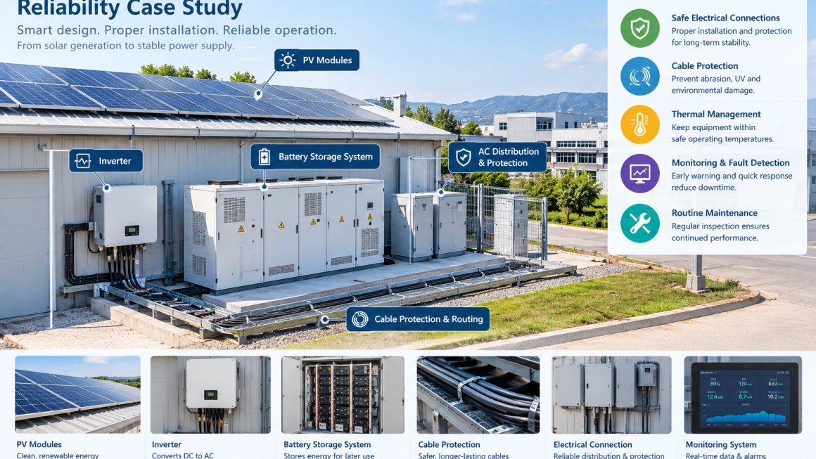
The system includes:
- Rooftop photovoltaic modules
- PV inverters or a compatible hybrid inverter
- Battery modules and a battery management system (BMS)
- Power conversion and energy management functions, depending on system architecture
- AC and DC cabling, connectors, isolation, and protection equipment
- Battery enclosure, ventilation or thermal management, and monitoring equipment
- Cable routing and mechanical protection accessories
The facility has limited indoor space, and some cable routes pass through areas exposed to temperature changes, dust, vibration, or occasional mechanical contact.
The main project objective is not simply to maximize installed capacity. It is to maintain dependable operation while making practical use of solar generation and minimizing avoidable maintenance interruptions.
Key Reliability Objectives
The project team defines five priorities:
- Maintain safe and stable electrical connections.
- Reduce preventable cable and connector damage.
- Keep batteries and power electronics within manufacturer-specified operating conditions.
- Identify abnormal operating conditions through monitoring and inspection.
- Make routine maintenance straightforward and repeatable.
These objectives establish a practical framework for evaluating the system throughout its operating life.
2. Initial Reliability Assessment
Before commissioning, the project team reviews the system design and installation conditions.
Rather than assuming that reliability problems will originate inside the battery, the assessment considers the complete electrical and mechanical installation.
2.1 Cable Routing and Mechanical Exposure
Cables may pass near metal edges, structural supports, moving equipment, or maintenance access routes. Repeated rubbing, excessive bending, tensile stress, and poorly secured cable runs can damage insulation or external sheathing.
The team checks whether cables are properly supported, whether the specified minimum bend radius is respected, and whether cables are protected at penetrations and contact points.
Where necessary, suitable conduit, protective sleeves, edge protection, cable glands, or strain-relief components can be selected for the specific location.
2.2 Outdoor Environmental Exposure
Rooftop and outdoor components may experience sunlight, rain, dust, temperature cycling, and moisture accumulation.
The assessment verifies that equipment enclosures, cable glands, connectors, and sealing systems are suitable for their intended exposure. Any required IP rating or other environmental classification must be confirmed against the project design and applicable standards.
A protective sleeve alone does not make an otherwise unsuitable connection waterproof or weatherproof.
2.3 Thermal Management
Battery modules, inverters, and power conversion equipment have specified operating-temperature ranges and installation clearances.
The team checks whether equipment placement allows the required airflow or heat rejection, whether ventilation paths could become blocked, and whether nearby heat sources may affect operation.
Cable protection products must also be suitable for the expected temperature and must not obstruct equipment cooling.
2.4 Electrical Connections and Protection
The inspection covers cable terminations, connectors, isolation devices, grounding, overcurrent protection, and other specified electrical safeguards.
Connections should be installed according to manufacturer instructions and verified using appropriate commissioning procedures. Electrical work and testing must be carried out by qualified personnel.
2.5 Monitoring and Fault Detection
The team verifies that relevant system measurements and alarms are available, including those supported by the installed equipment.
Depending on the architecture, useful information may include battery state of charge, battery temperature, inverter status, generation, energy flows, and fault codes.
Monitoring helps identify abnormal conditions, but it does not replace physical inspection or required electrical testing.
3. Reliability Risks and Corrective Actions
The following table summarizes typical risks for a small PV + storage installation and practical measures for addressing them.
| Potential risk | Possible consequence | Recommended measure |
|---|---|---|
| Cable abrasion or crushing | Insulation damage and service interruption | Improve routing, secure cables, and add suitable mechanical protection |
| UV or weather exposure | Premature deterioration of unsuitable materials | Verify outdoor ratings and material compatibility |
| Loose or incorrectly installed connections | Heating, electrical faults, or unstable operation | Follow manufacturer procedures and verify connections during commissioning |
| Restricted ventilation | Elevated equipment temperature or derating | Maintain required clearances and inspect airflow paths |
| Moisture ingress | Corrosion or electrical malfunction | Verify enclosure ratings, glands, seals, and installation practices |
| Poor strain relief | Stress at connectors and terminations | Use appropriate supports and strain-relief accessories |
| Unnoticed abnormal operating conditions | Delayed fault response | Configure monitoring, alarms, and a defined response procedure |
| Inconsistent maintenance | Gradual deterioration remains undetected | Use a documented inspection and maintenance schedule |
The important lesson is that reliability measures should address the actual failure mechanism. For example, a cable sleeve may reduce abrasion, but it cannot correct an undersized conductor, an incorrectly crimped terminal, or inadequate overcurrent protection.
4. Improvement Plan: From Installation Checks to Long-Term Reliability
After identifying potential risks, the project team organizes corrective measures into four stages.
Stage 1: Improve Installation Quality
Cable routes are reviewed to eliminate avoidable contact with sharp edges, reduce unsupported spans, and maintain appropriate separation from incompatible heat sources or other services.
Where cables pass through metal openings, suitable edge protection and properly specified cable entry components are considered. Cable support and strain relief are arranged to prevent unnecessary loads on connectors and terminals.
All accessories must be compatible with the cable diameter, installation method, temperature range, and environmental conditions.
Stage 2: Strengthen Environmental Protection
Outdoor cable routes and exposed components are assessed for sunlight, moisture, dust, and mechanical damage.
Where required, the team selects materials and enclosures with verified ratings suitable for the location. Protective accessories should be inspected for cracking, deformation, loosening, or other deterioration over time.
The objective is to reduce specific environmental risks rather than assume that one protective product can address every condition.
Stage 3: Verify Thermal and Electrical Conditions
The project team checks equipment clearances, ventilation, connection quality, grounding, isolation, and protection arrangements.
Commissioning records should document relevant checks and equipment settings. Any abnormal temperature, repeated fault, or unexplained performance change should be investigated according to the manufacturer’s procedures.
Protective accessories must never be used as substitutes for proper electrical design, battery thermal management, or required fire-safety provisions.
Stage 4: Establish Routine Inspection
The facility develops a maintenance plan covering visible cable routes, enclosure condition, protective accessories, ventilation paths, alarms, and relevant operating records.
Inspection frequency should reflect the manufacturer’s guidance, site conditions, operating hours, and identified risks.
Damaged components should be repaired or replaced using approved procedures rather than temporarily covered without understanding the underlying cause.
5. Monitoring System Performance
A reliable PV + storage system needs a clear baseline against which future operation can be assessed.
For this illustrative project, the facility records several indicators.
Solar Generation
Daily and monthly PV generation helps identify changes that may be associated with weather, shading, equipment faults, or other site conditions.
Generation should be compared under reasonably comparable conditions before concluding that a performance decline indicates a fault.
Battery Operation
Battery state of charge, temperature, charge and discharge power, and available alarms can help the operator determine whether the system is operating within its permitted limits.
Battery operating data should be interpreted according to the manufacturer’s specifications. Unusual readings require investigation rather than assumptions about the cause.
Energy Utilization
The facility compares solar generation, on-site consumption, battery charging and discharging, and grid imports where the metering arrangement supports these measurements.
These records help determine whether the system is meeting its energy-management objectives.
Faults and Maintenance Events
The operator records faults, alarms, inspections, repairs, and component replacements.
A simple maintenance history can reveal recurring problems, such as repeated cable movement, environmental deterioration, or equipment overheating.
System Availability
Availability measures the extent to which the system is ready to perform its intended function. The definition should be agreed in advance, including how planned maintenance and external grid outages are treated.
These indicators help distinguish normal operational variation from emerging reliability concerns.
6. What If the System Experiences a Fault?
A practical fault-response process helps reduce uncertainty and prevent inappropriate interventions.
Scenario A: An inverter reports a temperature-related alarm.
The operator reviews the alarm and relevant operating data, then follows the manufacturer’s instructions. Qualified personnel inspect ventilation, ambient conditions, and other potential causes. The operator should not assume that adding cable protection will resolve an equipment-cooling problem.
Scenario B: A cable sheath shows visible abrasion.
The affected circuit is assessed and made safe according to the approved electrical isolation procedure. Qualified personnel determine whether the cable requires replacement and whether additional routing protection or support is necessary.
Scenario C: Outdoor connections show signs of moisture or corrosion.
The affected components are assessed according to the manufacturer’s procedures and applicable safety requirements. The team checks the suitability and condition of the connector, cable entry, seal, enclosure, and installation method before returning the equipment to service.
Scenario D: Battery alarms occur repeatedly.
The operator reviews the relevant BMS records and follows the manufacturer’s fault-response procedure. Repeated alarms should not be dismissed simply because the system continues to operate.
Across all scenarios, protective accessories are only one part of the response. The underlying fault must be identified and corrected.
7. The Role of Cable Protection in PV + Storage Reliability
Small PV + storage systems often include cable routes that pass through rooftops, equipment rooms, outdoor service areas, and compact electrical enclosures.
These routes may be exposed to different mechanical and environmental conditions.
Suitable cable protection and installation accessories can help address defined risks.
Abrasion and Mechanical Contact
Protective sleeves, conduit, edge protection, and cable supports may reduce damage caused by rubbing, sharp edges, or accidental contact when correctly selected and installed.
UV and Weather Exposure
Where cables or accessories are exposed outdoors, materials should be rated for the expected UV exposure, temperature, moisture, and service life.
Vibration and Cable Movement
Suitable cable supports, clamps, and strain-relief arrangements can help limit repeated movement and reduce stress at connection points.
Dust and Contamination
Enclosures, glands, routing arrangements, and suitable protective components can help limit contamination where the design requires it. The appropriate solution depends on the location and required protection level.
Easier Inspection and Maintenance
Clearly routed, identified, and accessible cables can simplify inspection and fault diagnosis. Protective components should be installed in a way that permits the required inspection and does not hide defects that need to be detected.
For GR-NEWenergy, these are relevant application areas for energy storage installation and O&M accessories. Product selection should be based on verified specifications and the actual installation environment.
8. Reliability Versus Cost: Choosing Practical Improvements
Small-scale projects often operate under budget constraints. The most appropriate reliability improvement is not necessarily the most expensive one.
A useful selection process considers:
- The likelihood of the failure mechanism
- The potential consequence of failure
- The cost and complexity of prevention
- The expected service life of the component
- Inspection and replacement requirements
- Compatibility with existing equipment
- Compliance with relevant standards and manufacturer requirements
For example, improving a poorly routed cable may be more effective than adding multiple layers of protective material. Replacing an unsuitable outdoor connector may be necessary even if a protective cover appears less expensive.
Reliability planning should prioritize measures that address verified risks and support safe maintenance.
9. Lessons From the Case Study
This illustrative project demonstrates several principles that apply to small-scale PV + storage installations.
First, reliability is a system-level property. Solar modules and batteries may operate correctly while installation problems elsewhere create service interruptions.
Second, small systems still require disciplined engineering. Limited system size does not eliminate the need for suitable protection, thermal management, commissioning, and maintenance.
Third, environmental protection must be application-specific. Materials and accessories should match the actual exposure and installation requirements.
Fourth, monitoring is most useful when linked to action. Alarms and operating records should trigger a defined investigation process rather than simply being collected.
Fifth, maintenance should be planned from the beginning. Cable accessibility, component identification, inspection procedures, and replacement requirements should be considered during installation design.
These principles can help system owners build a more consistent approach to reliability without assuming that every project requires the same equipment or protection strategy.
10. A Practical Reliability Checklist for Small PV + Storage Systems
Before commissioning, the project team should verify the following items.
- PV and battery equipment are installed according to manufacturer instructions.
- Cable sizing, routing, support, and bend radius meet project requirements.
- Suitable protection is provided at sharp edges, penetrations, and mechanical contact points.
- Outdoor cables, glands, enclosures, and accessories have appropriate ratings.
- Electrical isolation, grounding, and protective devices have been verified.
- Battery and inverter ventilation or thermal management requirements are met.
- Monitoring, alarms, and communication functions have been tested.
- Maintenance access and component identification are adequate.
- Inspection and fault-response procedures have been documented.
- Relevant commissioning and maintenance records are retained.
The checklist is a general planning aid, not a substitute for the applicable electrical code, site-specific engineering design, commissioning requirements, or manufacturer instructions.
Frequently Asked Questions
What are the main causes of reliability problems in small PV + storage systems?
Potential causes include unsuitable electrical connections, cable damage, environmental exposure, inadequate thermal management, incorrect installation, and delayed fault detection. The actual cause must be established through appropriate inspection and diagnosis.
How can cable protection improve PV + storage system reliability?
Suitable cable protection can reduce defined risks such as abrasion, mechanical contact, and certain environmental exposures. It does not replace correct cable sizing, electrical protection, appropriate connectors, or safe installation practices.
How often should a small PV + storage system be inspected?
Inspection frequency depends on manufacturer recommendations, environmental exposure, operating conditions, local requirements, and the system’s risk assessment. Outdoor or mechanically demanding installations may require more frequent checks of exposed components.
Does a battery monitoring system eliminate the need for maintenance?
No. Monitoring can identify certain abnormal conditions, but physical inspection, equipment-specific testing, maintenance, and safe fault response remain necessary.
What should be checked when selecting PV + storage cable protection accessories?
Check cable diameter, temperature rating, UV and weather resistance where relevant, mechanical requirements, chemical compatibility, installation method, and applicable standards. The selected accessory must be suitable for its intended use and must not interfere with equipment cooling or electrical safety.
How can small businesses improve PV + storage reliability without excessive cost?
Begin with a site-specific risk assessment. Prioritize correct installation, suitable protection, verified connections, thermal management, monitoring, and practical maintenance procedures. Addressing the actual failure risks is generally more effective than adding unnecessary components.
Small-scale PV + storage systems can support more flexible energy use, but their long-term reliability depends on the complete installation rather than battery or inverter performance alone.
A structured approach to cable routing, environmental protection, thermal management, commissioning, monitoring, and maintenance can help reduce preventable problems and make system operation easier to manage.
For commercial buildings, workshops, and small industrial facilities, reliability improvements should be based on actual site conditions and verified technical requirements. The goal is to build a system that is not only functional at commissioning, but also accessible, inspectable, and maintainable throughout its operating life.
GR-NEWenergy focuses on energy storage integration and O&M-related solutions, including cable protection, installation accessories, and practical protection measures for energy infrastructure. By selecting suitable accessories for the actual application, project teams can address specific installation risks as part of a broader, properly engineered reliability strategy.