From Project Installation to Long-Term Operation: How to Maintain Reliable Solar and Energy Storage Systems
Combining solar photovoltaic (PV) generation with battery energy storage has become an increasingly practical solution for commercial, industrial, and distributed energy applications.
A PV + Storage system can help facilities improve renewable energy utilization, manage electricity demand, shift energy consumption across different periods, and support selected backup power requirements.
However, the performance of a PV + Storage installation is not determined only by the quality of its solar panels or battery equipment.
Long-term reliability depends on how the system is designed, installed, commissioned, operated, inspected, and maintained throughout its service life.
Cable routing, electrical connections, environmental protection, ventilation, communication wiring, and maintenance accessibility all influence the condition of the installation over time.
A maintenance strategy that begins only after equipment failures occur may result in unnecessary downtime, more complicated repairs, and higher maintenance costs.
This article explores the lifecycle of PV + Storage systems, from initial project planning to long-term operation, and explains the maintenance practices that help preserve system reliability.
1. Understanding the Lifecycle of a PV + Storage System
A PV + Storage project should be considered a long-term energy infrastructure investment rather than a one-time equipment installation.
Its lifecycle generally includes several stages:
- Project planning and system design
- Equipment selection and procurement
- Installation and integration
- Commissioning and performance verification
- Normal operation and monitoring
- Preventive maintenance and corrective maintenance
- Equipment replacement, retrofit, and system expansion
Each stage creates different technical and maintenance requirements.
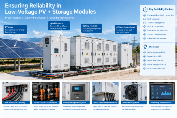
<Placeholder: PV plus battery energy storage system lifecycle diagram>
| Lifecycle stage | Main activities | Key considerations |
|---|---|---|
| Planning and design | Load analysis, system configuration, site assessment | Future maintenance and expansion |
| Procurement | Equipment and accessory selection | Compatibility and technical specifications |
| Installation | Mechanical and electrical installation | Cable routing, protection, and accessibility |
| Commissioning | Inspection and functional verification | Documentation and baseline performance |
| Operation | Energy management and monitoring | Operating limits and abnormal conditions |
| Maintenance | Inspection, testing, and repairs | Equipment condition and maintenance records |
| Retrofit and expansion | Replacement and capacity upgrades | Compatibility and integration |
The decisions made during early project stages can have a significant influence on maintenance requirements later.
For example, an installation with accessible cable trays, properly protected cable entries, and sufficient equipment clearance may be easier to inspect and maintain than one where every component is tightly integrated into a restricted space.
2. Planning for Maintenance Before Installation
One of the most effective ways to reduce future maintenance difficulties is to consider maintenance requirements during the initial project design.
A system should not only be designed to operate correctly at commissioning. It should also be designed to remain accessible and serviceable.
2.1 Site assessment
Before installation, the project team should evaluate the physical and environmental conditions of the site.
Important factors include:
- Available installation space
- Ground conditions and drainage
- Ambient temperature
- Humidity and condensation
- Dust and airborne particles
- Solar exposure and UV radiation
- Coastal or corrosive environments
- Access for inspection and equipment replacement
These conditions influence the selection of equipment enclosures, cable protection materials, mounting structures, and sealing components.
2.2 Equipment layout and maintenance clearance
PV inverters, battery cabinets, distribution equipment, and auxiliary systems should be positioned with appropriate access for operation and maintenance.
The layout should consider:
- Equipment service doors and removable panels
- Battery module replacement requirements
- Cable entry and exit locations
- Ventilation and cooling arrangements
- Emergency access
- Inspection pathways
- Space for future expansion
Clearance requirements should follow the equipment manufacturer’s documentation and applicable installation regulations.
2.3 Cable routing design
Cable routing is an important part of the overall installation design.
PV DC cables, AC power cables, battery cables, and communication cables may have different electrical and environmental requirements.
The routing plan should address:
- Cable support and fastening
- Minimum bending radius
- Separation requirements
- Protection against sharp edges
- Exposure to sunlight and weather
- Mechanical abrasion
- Cable identification
- Accessibility for inspection
Suitable protective sleeves, conduits, cable glands, and fastening accessories can help protect vulnerable sections.
These accessories should be selected according to the actual installation conditions rather than treated as interchangeable components.
2.4 Future expansion considerations
Many commercial and industrial PV + Storage projects may be expanded after the initial installation.
Future additions may include:
- Additional PV generation capacity
- More battery cabinets
- Additional inverters
- New monitoring equipment
- Additional communication connections
- Changes to energy management strategies
The initial design should consider potential expansion pathways where practical.
This can reduce the need for extensive cable rerouting or structural modifications during later upgrades.
3. Installation Quality: Establishing the Foundation for Long-Term Reliability
Installation quality has a direct influence on future maintenance requirements.
Even when individual components meet their technical specifications, poor installation practices can introduce problems that become visible only after months or years of operation.
3.1 PV module and mounting structure installation
Solar modules and mounting structures should be installed according to the approved design and manufacturer requirements.
Inspection considerations include:
- Mounting structure stability
- Fastener installation
- Module positioning
- Cable support beneath modules
- Drainage and water management
- Potential contact between cables and structural edges
PV cables should be secured appropriately and protected from repeated movement, abrasion, and prolonged exposure to unsuitable environmental conditions.
3.2 Inverter and battery equipment installation
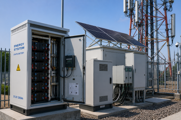
Inverters and battery cabinets should be installed according to the required environmental, electrical, and mechanical conditions.
The installation team should verify:
- Equipment foundations and supports
- Required service clearances
- Ventilation arrangements
- Cable entry locations
- Grounding and bonding arrangements
- Enclosure integrity
- Access to isolation and maintenance points
Equipment should not be positioned in a way that makes routine inspection or future replacement unnecessarily difficult.
3.3 Electrical connections
Electrical connections are critical components of PV + Storage installations.
Improper connections may result in abnormal heating, unstable operation, or equipment damage.
Installation and inspection should follow the relevant equipment instructions and applicable electrical standards.
Qualified personnel should verify connection integrity using appropriate procedures and tools.
3.4 Cable protection and sealing
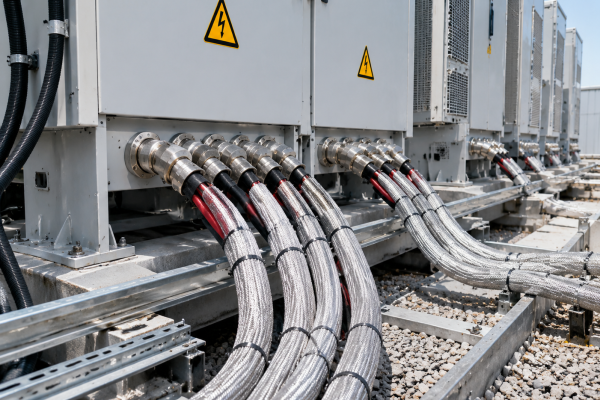
Cable entries, exposed cable sections, and transitions between equipment and cable trays deserve particular attention.
Potential problems include:
- Abrasion at enclosure openings
- Cable movement caused by vibration
- Deterioration from UV exposure
- Moisture entering through unsuitable cable entry arrangements
- Damaged protective sleeves
- Poorly secured cable bundles
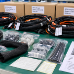
Suitable cable glands, grommets, conduits, braided sleeves, and other protective accessories can help address these conditions.
However, a cable sleeve does not automatically provide waterproofing, electrical insulation repair, or fire containment. Each protection function should be evaluated separately.
4. Commissioning: Creating a Reliable Operating Baseline
Commissioning is an important stage in the PV + Storage lifecycle.
It verifies that the installed equipment and supporting infrastructure are ready for operation according to the approved project requirements.
The commissioning process should be carried out by qualified personnel using documented procedures.
4.1 PV system verification
Depending on the system configuration, PV commissioning may include:
- Module and string configuration verification
- Polarity checks
- Appropriate electrical testing
- Inverter configuration verification
- Grounding and bonding checks
- Monitoring system communication checks
4.2 Battery storage verification
Battery storage commissioning may involve:
- Battery equipment identification
- BMS communication verification
- Operating parameter confirmation
- Battery status checks
- PCS communication and functional checks
- Alarm and protection function verification
The exact commissioning scope depends on the battery technology, equipment supplier, and project specifications.
4.3 EMS and communication verification
Where an EMS is included, commissioning should verify that the required equipment can exchange the intended information.
This may include communication between:
- Battery management systems
- Power conversion systems
- PV inverters
- Energy meters
- EMS controllers
- Site monitoring platforms
The project team should verify data availability, alarm reporting, command permissions, and operating boundaries.
4.4 Establishing baseline records
Commissioning records provide a reference for future maintenance.
Useful information includes:
| Record | Purpose |
|---|---|
| Equipment model and serial numbers | Equipment identification |
| Electrical test records | Initial verification reference |
| Configuration parameters | Future troubleshooting |
| Communication settings | Integration maintenance |
| Cable routing drawings | Inspection and modification planning |
| Photographs | Visual reference for future work |
| Alarm and test records | Baseline operating information |
| Maintenance instructions | Ongoing service planning |
Without reliable commissioning documentation, future maintenance teams may spend additional time identifying equipment configurations and previous installation decisions.
5. Routine Maintenance During Normal Operation
Once the system enters normal operation, maintenance should focus on monitoring equipment condition and identifying abnormal changes.
The maintenance frequency should follow manufacturer instructions, site conditions, applicable standards, and the project’s O&M plan.
5.1 PV module inspection
PV modules are exposed to outdoor environmental conditions throughout their operating life.
Inspection may include:
- Visible cracks or physical damage
- Surface contamination
- Loose or damaged mounting components
- Cable support conditions
- Connector condition
- Signs of water accumulation
- Unusual shading or vegetation growth
Cleaning should be carried out according to module manufacturer guidance and site conditions.
Cleaning methods should avoid damaging module surfaces or creating electrical and physical hazards.
5.2 Inverter maintenance
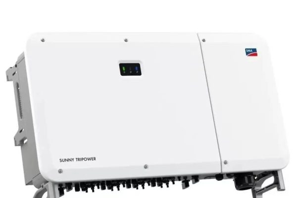
Inverters are important components in both PV generation and energy storage applications.
Maintenance may include:
- Checking operating status
- Reviewing fault and alarm records
- Inspecting cooling arrangements
- Checking ventilation openings
- Reviewing environmental conditions
- Inspecting accessible external connections
- Verifying communication availability
Internal electrical inspection and servicing should be performed by qualified personnel following the manufacturer’s procedures.
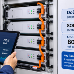
5.3 Battery system monitoring
Battery maintenance should consider both equipment status and operating history.
Relevant monitoring information may include:
- State of charge (SOC)
- State of health (SOH), where supported
- Battery temperature
- Voltage and current information
- Alarm history
- Charging and discharging behavior
- Abnormal temperature differences
- Communication status
A change in battery performance should be evaluated using appropriate diagnostic information rather than relying on a single operating parameter.
5.4 EMS performance review
Energy management strategies may need adjustment when facility demand, electricity tariffs, or renewable generation patterns change.
Periodic review can help determine whether the original control strategy remains appropriate.
Typical questions include:
- Is the system following the intended charging schedule?
- Is battery capacity being used effectively?
- Are demand peaks being managed as expected?
- Is PV generation being utilized according to the configured strategy?
- Are communication interruptions affecting energy management?
- Have site operating conditions changed?
An EMS performance review should consider actual operating data and the original project objectives.
6. Cable and Connection Maintenance: An Often Overlooked Area
Battery and inverter equipment frequently receive significant attention during routine maintenance.
However, the supporting cable infrastructure also requires inspection.
Cable systems are exposed to mechanical, thermal, environmental, and installation-related stresses throughout the operating life of a PV + Storage installation.
6.1 PV DC cable inspection
PV DC cables may be exposed to sunlight, elevated temperatures, moisture, and mechanical contact.
Inspection should consider:
- Cable jacket condition
- UV exposure
- Cable support and fastening
- Contact with metal structures
- Connector condition
- Cable entry points
- Protective conduit condition
Damaged cable jackets or connectors require appropriate assessment and corrective action by qualified personnel.
6.2 Battery and AC power cable inspection
Battery and AC power cables may be routed through equipment cabinets, cable trays, and external connection areas.
Inspection areas include:
- Visible signs of overheating
- Cable support condition
- Mechanical abrasion
- Cable movement
- Damaged protective accessories
- Enclosure entry arrangements
- Cable identification
Where electrical testing or connection inspection is necessary, it should follow approved procedures and equipment manufacturer requirements.
6.3 Communication cable inspection
Communication wiring connects battery systems, inverters, meters, and EMS equipment.
A damaged or unstable communication connection may interfere with monitoring or supervisory control.
Inspection should consider:
- Cable routing
- Connector condition
- Shielding and termination arrangements
- Mechanical protection
- Separation from other wiring where required
- Environmental exposure
- Signs of intermittent communication
Physical cable protection and correct communication installation practices should be considered together.
6.4 Protective sleeves and conduits
Cable protection products may deteriorate due to environmental exposure, mechanical movement, or aging.
Maintenance teams should check for:
- Cracked or deformed conduits
- Displaced braided sleeves
- Damaged wraparound closures
- Loose fastening points
- Worn protective surfaces
- Exposed cable sections
- Inadequate coverage around bends
Replacing a damaged protective accessory may be sufficient when the underlying cable remains in acceptable condition.
If the cable itself is damaged, an external sleeve should not be used to conceal the defect.
7. Preventive Maintenance vs. Corrective Maintenance
A structured O&M strategy generally combines preventive maintenance with corrective maintenance.
| Maintenance approach | Main purpose | Example activities |
|---|---|---|
| Preventive maintenance | Reduce the likelihood of avoidable failures | Scheduled inspection, cleaning, equipment checks |
| Corrective maintenance | Address identified defects | Replacing damaged accessories, repairing or replacing defective components |
| Condition-based maintenance | Act on observed equipment condition | Investigating abnormal temperature trends or recurring alarms |
| Predictive maintenance | Estimate future maintenance needs using suitable data and models | Trend analysis and condition monitoring |
The appropriate balance depends on system size, operating environment, criticality, maintenance resources, and equipment supplier recommendations.
Why preventive maintenance matters
Preventive maintenance helps identify deterioration before it develops into a more serious problem.
For example, a displaced cable sleeve may initially appear to be a minor issue.
However, if the cable is then exposed to repeated contact with a metal edge, the cable jacket may gradually deteriorate.
Identifying and correcting the protection issue early can help prevent more extensive maintenance work.
Why corrective maintenance still matters
Not every issue can be prevented.
Unexpected equipment failures, severe weather events, accidental mechanical damage, and changing site conditions may require corrective maintenance.
A clear process for identifying, documenting, prioritizing, and resolving defects helps maintenance teams respond more effectively.
8. Seasonal and Environmental Maintenance Considerations
The maintenance requirements of a PV + Storage installation can vary significantly according to its location.
8.1 Hot and high-UV environments
High ambient temperatures and prolonged solar exposure can affect equipment enclosures, cable jackets, and protective materials.
Maintenance teams should pay attention to:
- Cable jacket condition
- Protective sleeve aging
- Enclosure ventilation
- Signs of abnormal heating
- Exposure of cable sections to direct sunlight
Where additional protection is required, materials should be selected according to verified temperature and UV resistance specifications.
8.2 Humid and rainy environments
High humidity and frequent rainfall may increase the importance of enclosure sealing and drainage arrangements.
Inspection should include:
- Cable glands
- Enclosure entry points
- Sealing components
- Cable routing that may retain water
- Signs of condensation
- Corrosion around exposed interfaces
An external protective sleeve should not be assumed to provide a watertight connection.
8.3 Dusty and sandy environments
Dust and sand can accumulate around equipment and cable routing structures.
Potential maintenance activities include:
- Inspecting ventilation openings
- Checking enclosure sealing
- Reviewing exposed cable protection
- Removing accumulated contamination using approved methods
- Checking for abrasion caused by wind-driven particles
8.4 Coastal and corrosive environments
Coastal installations may experience salt-laden air and accelerated corrosion of exposed metal components.
Inspection should consider:
- Cable tray and support corrosion
- Fasteners and brackets
- Enclosure interfaces
- Cable glands and fittings
- Protective coatings
- Exposed connectors
Material selection should be based on the actual corrosion environment and verified product data.
9. Maintenance Planning Across the System Lifecycle
A practical maintenance program should identify what needs to be inspected, who is responsible, and what records should be maintained.
The following table is a general planning reference rather than a universal inspection schedule.
| Maintenance stage | Typical focus | Example records |
|---|---|---|
| Before commissioning | Installation quality and documentation | Inspection reports and test records |
| Initial operation | Operating baseline and alarms | Performance and configuration records |
| Routine operation | Equipment status and visible condition | Monitoring and inspection records |
| Scheduled maintenance | PV, battery, PCS, cables, and accessories | Maintenance checklists |
| After abnormal events | Physical damage and system condition | Incident and corrective action reports |
| Before expansion | Existing system compatibility and available infrastructure | Modification and design records |
| Equipment replacement | Interfaces, settings, and installation condition | Replacement and recommissioning records |
The actual frequency and scope should be defined by the project O&M plan, manufacturer requirements, and applicable regulations.
10. Retrofit and Upgrade Strategies for Existing PV + Storage Systems
PV + Storage systems may remain in operation for many years, but their supporting infrastructure and operating requirements can change.
Maintenance and upgrade projects may therefore involve more than replacing failed equipment.
10.1 Localized cable protection upgrades
Some existing installations may have cable sections that require additional mechanical or environmental protection.
Where the cable remains in acceptable condition, suitable retrofit products may include:
- Split braided sleeves
- Wraparound cable sleeves
- Self-wrapping protective sleeves
- Split corrugated conduits
- High-temperature fiberglass sleeves
- Aluminum foil and fiberglass-based protection products
These solutions can be useful where cable removal is difficult and only selected sections require additional protection.
10.2 Cable routing improvements
During system upgrades, maintenance teams may identify opportunities to improve cable routing.
Examples include:
- Adding suitable cable supports
- Improving protection around sharp edges
- Separating or reorganizing cable bundles where required
- Improving access to inspection points
- Replacing damaged conduits
- Improving cable identification
Any routing modification must respect the original electrical design, equipment instructions, and applicable installation requirements.
10.3 Equipment and communication upgrades
Existing systems may require new monitoring equipment, replacement inverters, updated communication devices, or revised EMS functions.
Before modifications, the project team should confirm compatibility with the existing equipment and communication architecture.
Changes should be documented and appropriately verified before returning the system to service.
10.4 Maintenance-driven expansion planning
If a facility intends to expand PV or battery capacity, the upgrade should consider the condition of the existing installation.
This may involve reviewing:
- Cable capacity and routing
- Electrical protection arrangements
- Equipment clearances
- Communication infrastructure
- Auxiliary power requirements
- Maintenance access
- Environmental protection
Expansion should be treated as an engineering modification rather than simply adding more equipment to an existing installation.
11. Common PV + Storage Maintenance Mistakes
| Common mistake | Potential consequence | Better practice |
|---|---|---|
| Focusing only on battery and inverter alarms | Supporting infrastructure defects may be overlooked | Include cable and accessory inspections |
| Ignoring cable support conditions | Cables may experience repeated movement or abrasion | Review fastening and routing |
| Assuming protective sleeves never need replacement | Deteriorated protection may remain unnoticed | Inspect accessory condition periodically |
| Covering damaged cables with new sleeves | Underlying cable defects may remain hidden | Assess cable condition before retrofit |
| Ignoring environmental changes | Existing materials may no longer be suitable | Review actual exposure conditions |
| Failing to document modifications | Future troubleshooting becomes more difficult | Maintain updated records |
| Blocking ventilation during retrofit work | Equipment operating conditions may be affected | Preserve required airflow and clearance |
| Using incompatible replacement accessories | Installation performance may be compromised | Verify dimensions and specifications |
| Skipping post-maintenance verification | Changes may go unnoticed | Follow approved inspection and testing procedures |
12. How GR-NEWenergy Supports PV + Storage Installation and O&M
The long-term maintenance of PV + Storage systems requires attention to both major equipment and supporting installation components.
GR-NEWenergy focuses on energy storage installation and O&M protection solutions, particularly cable protection products and related accessories.
Relevant product categories include:
Cable protection solutions
- Braided cable sleeves
- Split and wraparound sleeves
- Self-wrapping protective sleeves
- High-temperature fiberglass sleeves
- Aluminum foil and fiberglass-based protection products
Cable routing and installation accessories
- Flexible protective conduits
- Cable glands and sealing components
- Cable fastening accessories
- Cable entry and routing accessories
Retrofit and maintenance solutions
- Replacement protective sleeves
- Localized cable protection upgrades
- Mechanical abrasion protection
- Selected UV and environmental protection accessories
- Thermal protection products for suitable applications
These products can support selected PV, battery storage, inverter, and auxiliary cable applications.
For maintenance contractors and system operators, the objective is to identify practical protection solutions based on the existing cable arrangement and operating environment.
GR-NEWenergy does not replace the responsibilities of electrical engineers, battery manufacturers, PCS suppliers, EMS developers, or qualified O&M contractors.
Instead, its product range focuses on an important supporting area of the installation: protecting cables and related components throughout normal operation and maintenance.
The lifecycle of a PV + Storage system extends far beyond initial installation and commissioning.
Long-term reliability depends on equipment condition, energy management, electrical infrastructure, environmental protection, and consistent maintenance practices.
A well-structured O&M strategy should include not only PV modules, battery systems, and inverters, but also cable routing, communication wiring, protective accessories, sealing components, and maintenance accessibility.
By considering maintenance from the planning stage and reviewing installation conditions throughout the system’s operating life, project owners and O&M contractors can make future inspections and upgrades more manageable.
For existing installations, localized retrofit solutions may also provide a practical way to improve cable protection without automatically replacing entire cable runs.
Ultimately, effective PV + Storage lifecycle management is about maintaining the complete installation, not just the major equipment.
Q1: What does PV + Storage system lifecycle management include?
It includes project planning, equipment procurement, installation, commissioning, operation, preventive maintenance, corrective maintenance, equipment replacement, and future system upgrades.
Q2: How often should a PV + Storage system be maintained?
Maintenance frequency depends on equipment manufacturer requirements, operating environment, system configuration, and applicable regulations. A project-specific O&M plan should define inspection and servicing intervals.
Q3: What should be inspected during PV + Storage maintenance?
Typical inspection areas include PV modules, inverters, battery systems, electrical connections, communication wiring, cable routing, protective sleeves, cable glands, enclosures, ventilation, and environmental conditions.
Q4: Why is cable protection important in PV + Storage systems?
Power and communication cables may be exposed to UV radiation, moisture, abrasion, vibration, temperature changes, and mechanical contact. Appropriate cable protection helps address these exposure conditions and supports long-term installation maintainability.
Q5: Can cable protection accessories be replaced without removing existing cables?
In selected applications, yes. Split braided sleeves, wraparound sleeves, self-wrapping sleeves, and split conduits can be installed around accessible existing cables. Suitability depends on cable condition, dimensions, and installation access.
Q6: What is the difference between preventive and corrective maintenance?
Preventive maintenance involves scheduled activities intended to reduce avoidable failures. Corrective maintenance addresses defects after they are identified. Both are necessary parts of a complete O&M strategy.
Q7: Can an existing PV + Storage system be upgraded without replacing the complete installation?
Some upgrades can be performed locally, such as replacing selected accessories, improving cable protection, upgrading compatible monitoring equipment, or modifying approved system components. The scope depends on the existing design, compatibility, and engineering assessment.
Q8: What documentation should be maintained throughout the system lifecycle?
Important records include equipment information, commissioning reports, electrical test records, configuration data, alarm history, inspection reports, maintenance activities, photographs, and records of modifications.