

How Modular Battery Storage and Energy Management Systems Help Industrial Facilities Adapt to Changing Energy Demands
Industrial energy consumption is rarely constant.
Manufacturing facilities, industrial parks, warehouses, and processing plants often experience significant variations in electricity demand throughout the day. Production schedules change, equipment starts and stops, renewable energy generation fluctuates, and electricity tariffs may vary depending on the time of use.
For industrial operators, managing these changes is becoming increasingly important.
Modular energy storage systems provide one approach to improving energy flexibility. By combining battery storage with an Energy Management System (EMS), industrial facilities can coordinate energy charging, discharging, and consumption according to operating conditions and defined control strategies.
However, the value of this combination depends on more than battery capacity or software functionality. System architecture, communication, installation quality, operational constraints, and maintenance arrangements all influence long-term performance.
This article explores how modular energy storage and EMS integration can support industrial flexibility, what technical factors should be considered, and why installation and O&M details matter throughout the system lifecycle.
1. Why Industrial Facilities Need Greater Energy Flexibility
Industrial electricity demand is influenced by multiple operating factors.
A facility may have relatively stable base consumption but experience substantial demand peaks when production lines, compressors, heating equipment, pumps, or other high-power loads operate simultaneously.
Several challenges commonly arise.
1.1 Fluctuating electricity demand
Industrial production schedules can create substantial differences between minimum and maximum electricity demand.
For example:
- Production equipment may operate in scheduled batches.
- Multiple machines may start simultaneously.
- HVAC and cooling loads may increase during certain periods.
- Auxiliary systems may continue consuming electricity outside production hours.
- Production changes may introduce new demand patterns.
Without appropriate energy management, these variations can increase electricity costs or create operational constraints.
1.2 Electricity tariff differences
In regions where electricity tariffs vary by time of use, industrial facilities may have opportunities to charge energy storage systems during lower-cost periods and discharge during higher-cost periods.
The economic value depends on the tariff structure, charging and discharging efficiency, demand charges, battery degradation, and actual operating schedules.
Energy management strategies therefore need to consider the complete operating economics rather than simply maximizing battery utilization.
1.3 Renewable energy integration
Industrial facilities increasingly combine rooftop solar PV or other renewable energy sources with battery storage.
However, renewable generation does not always match industrial consumption.
A solar installation may generate excess electricity during periods of low production demand, while the facility may require additional electricity after sunset or during periods of reduced solar generation.
Energy storage can help shift some of this energy across time, subject to system capacity, operating limits, and applicable grid requirements.
1.4 Operational resilience
Some industrial facilities require greater control over how electricity is supplied to selected loads during grid disturbances or planned maintenance.
Energy storage may contribute to backup or resilience strategies when designed with compatible power conversion equipment, protection systems, controls, and operating procedures.
Battery storage alone does not guarantee uninterrupted power. The required electrical architecture and backup capability must be established during system design.
2. What Makes Modular Energy Storage Different?
A modular energy storage system is constructed from multiple coordinated units rather than relying entirely on one large, fixed-capacity configuration.
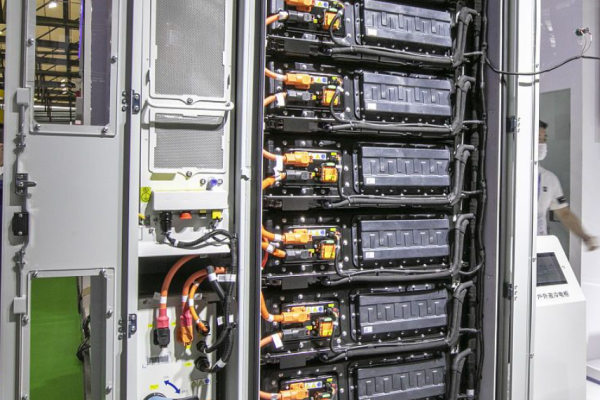
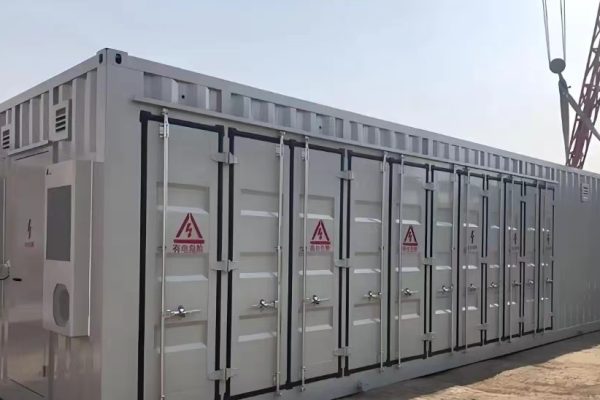
Depending on the system architecture, modules may include battery racks, battery cabinets, power conversion equipment, control equipment, thermal management systems, and associated electrical infrastructure.
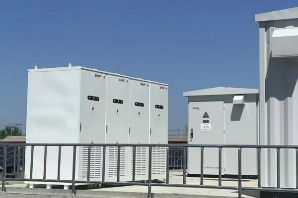
<Placeholder: Industrial modular battery energy storage installation>
The modular approach offers several potential advantages.
2.1 Flexible capacity configuration
Industrial facilities have different energy requirements.
A smaller installation may initially support a limited set of loads, while a larger facility may require a higher storage capacity and power rating.
Modular architectures can provide flexibility in configuring the overall system to match project requirements.
However, adding battery modules does not automatically increase usable system capacity. Compatibility, power conversion capacity, protection coordination, control configuration, available space, and manufacturer-approved expansion procedures must all be considered.
2.2 Phased deployment
Some industrial operators prefer to introduce energy storage in stages.
For example:
- Phase 1: Install storage for a specific production area.
- Phase 2: Expand capacity after operational data has been collected.
- Phase 3: Integrate additional renewable generation or loads.
- Phase 4: Refine energy management strategies based on actual demand.
A phased approach can help align investment with operational needs, although the initial system should be designed with any intended expansion requirements in mind.
2.3 Maintenance flexibility
Modular architectures may make it easier to identify and service individual equipment sections, depending on the manufacturer’s design and isolation procedures.
This can be useful when planning maintenance activities and managing the availability of the overall installation.
However, module-level serviceability should not be confused with permission to remove or replace battery modules during operation. Electrical isolation, safety procedures, and manufacturer instructions remain essential.
2.4 Standardized installation
Where modular equipment uses standardized interfaces and installation arrangements, project execution can become more repeatable.
This can simplify:
- Equipment positioning
- Electrical connection planning
- Cable routing
- Auxiliary wiring
- Maintenance access
- Future expansion planning
The actual level of standardization varies between suppliers and system architectures.
3. Understanding the Role of EMS in Industrial Energy Storage
The Energy Management System is responsible for coordinating energy-related decisions across the installation.
It may collect operational information, evaluate operating conditions, and issue control commands to compatible equipment.
The EMS is therefore an important part of the overall energy management architecture.
3.1 Energy monitoring and data collection
An EMS may collect information from:
- Grid meters
- Battery management systems
- Power conversion systems
- Solar PV inverters
- Industrial load meters
- Environmental sensors
- Other compatible equipment
Typical monitored parameters include:
| Equipment or system | Example monitoring information |
|---|---|
| Grid connection | Power demand, import and export energy |
| Battery system | State of charge, operating status, alarms |
| PCS | Charging and discharging power, operating status |
| Solar PV | Generation power and energy |
| Industrial loads | Consumption patterns and demand peaks |
| Environmental monitoring | Temperature and other relevant operating conditions |
The available information depends on the equipment interfaces, communication protocols, and system configuration.
3.2 Charging and discharging coordination
An EMS can implement operating strategies based on defined conditions.
For example, a time-of-use strategy may:
- Identify lower-tariff charging periods.
- Check battery availability and operating limits.
- Coordinate charging power.
- Monitor state of charge.
- Schedule discharge during selected higher-tariff periods.
- Adjust operation according to demand and system constraints.
The strategy must respect battery limits, equipment ratings, grid requirements, and the facility’s actual operating conditions.
3.3 Peak demand management
Peak shaving is one of the common industrial energy storage applications.
When facility demand approaches a predefined threshold, the EMS may request battery discharge to reduce grid power demand.
<Placeholder: Industrial electricity demand curve showing peak shaving through battery discharge>
A simplified example:
| Operating period | Facility demand | Storage response |
|---|---|---|
| Morning | Moderate | Charging or standby |
| Midday | High | Discharge if required |
| Afternoon | Peak production | Additional discharge within operating limits |
| Evening | Lower demand | Recharge when conditions permit |
The actual control strategy depends on demand patterns, tariff rules, storage capacity, available power, and the required reserve state of charge.
3.4 Renewable energy optimization
When solar PV is integrated with battery storage, an EMS can coordinate energy flows according to project priorities.
Potential strategies include:
- Prioritizing direct consumption of solar generation.
- Charging batteries using available surplus PV energy.
- Discharging stored energy when renewable generation decreases.
- Managing grid import and export limits.
- Maintaining a defined battery reserve.
The objective is to improve energy utilization while respecting the facility’s operating requirements and applicable grid rules.
4. How Modular Storage and EMS Work Together
Modular battery storage provides the physical energy capacity, while the EMS coordinates how that capacity is used.
The relationship can be understood through four functional layers.
Layer 1: Energy storage equipment
This layer includes battery modules, racks, cabinets, and associated battery management equipment.
It provides the available energy storage capacity and communicates operating information.
Layer 2: Power conversion equipment
The Power Conversion System (PCS) manages the conversion between AC and DC electrical power.
It enables charging and discharging according to system configuration and authorized control commands.
Layer 3: Energy management and coordination
The EMS evaluates operating information and coordinates energy management strategies.
It may communicate with the PCS, BMS, meters, PV inverters, and other compatible systems.
Layer 4: Industrial electrical infrastructure
The industrial facility provides the electrical connection between the storage system, grid, and relevant loads.
This includes switchgear, protection equipment, distribution infrastructure, cable routing, grounding arrangements, and other project-specific components.
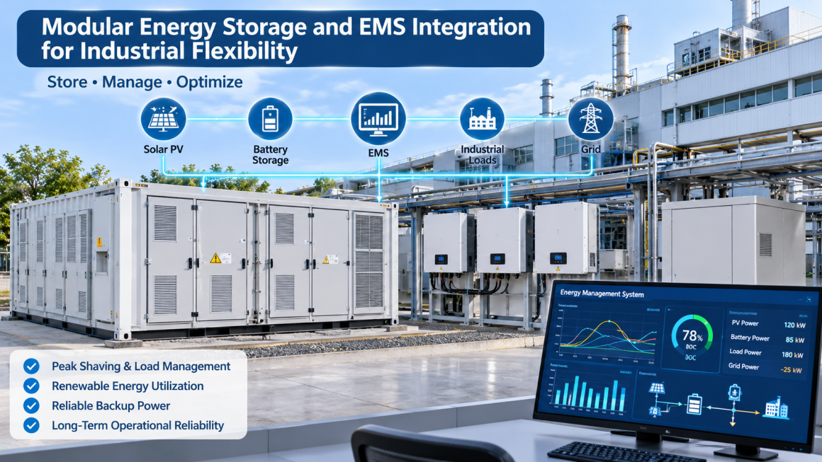
<Placeholder: Modular industrial energy storage and EMS integration architecture>
These layers must operate as a coordinated system.
A communication failure, incompatible interface, incorrect parameter configuration, or electrical installation issue can affect the intended energy management strategy.
5. Key EMS Integration Considerations
EMS integration is not simply a matter of connecting several devices to a common communication network.
The system requires clear definitions of equipment interfaces, control responsibilities, data requirements, and operating boundaries.
5.1 Communication protocol compatibility
Different equipment manufacturers may support different communication protocols and interface configurations.
Common industrial communication technologies include:
- Modbus RTU
- Modbus TCP
- CAN-based communication
- Ethernet-based interfaces
- Manufacturer-specific communication interfaces
The presence of a named protocol does not automatically guarantee interoperability.
The project team should confirm:
- Supported protocol versions
- Register maps or data dictionaries
- Communication parameters
- Read and write permissions
- Command acknowledgment behavior
- Alarm and fault reporting
- Communication timeout handling
A documented interface specification is particularly important when battery equipment, PCS, meters, and EMS are supplied by different manufacturers.
5.2 Control hierarchy
The system should clearly define which equipment is responsible for each control function.
For example:
| Equipment | Typical responsibility |
|---|---|
| BMS | Battery monitoring and battery-level protection functions |
| PCS | Power conversion and commanded power operation |
| EMS | Energy scheduling and supervisory coordination |
| Metering equipment | Measurement of electrical parameters |
| Site control system | Coordination with industrial loads and other facility systems |
The EMS should not override battery protection functions or bypass equipment safety controls.
Control priorities and operating limits must be defined by the system designer and relevant equipment manufacturers.
5.3 Data accuracy and response time
Energy management decisions depend on reliable operating information.
If demand measurements are delayed, inaccurate, or inconsistent, the resulting control strategy may not reflect actual facility conditions.
Relevant considerations include:
- Meter accuracy
- Data refresh intervals
- Time synchronization
- Communication latency
- Missing data handling
- Alarm reporting
- Historical data retention
The required performance depends on whether the application involves energy scheduling, demand management, fast power response, or another control function.
5.4 Communication reliability
Communication networks should be designed to suit the operating environment.
Industrial facilities may contain electromagnetic interference, long cable routes, multiple equipment areas, and physically separated control cabinets.
Communication wiring should be routed and protected appropriately, with suitable cable separation, shielding, grounding, and termination practices according to the equipment requirements.
Communication reliability is therefore influenced not only by software and protocols but also by physical installation quality.
6. Practical Industrial Applications
Modular storage and EMS integration can support different industrial energy strategies.
6.1 Manufacturing facilities
Manufacturing plants may experience demand peaks when multiple production lines operate simultaneously.
A coordinated storage system can discharge during selected high-demand periods and recharge when demand and tariff conditions are more favorable.
Potential benefits include:
- Improved demand management
- Greater flexibility in production scheduling
- Better coordination with rooftop PV
- More structured energy monitoring
The economic results depend on the facility’s load profile and tariff structure.
6.2 Industrial parks
Industrial parks may contain multiple buildings, tenants, production processes, and distributed energy resources.
An EMS may coordinate storage assets and energy measurements at different connection points, depending on the electrical architecture and control responsibilities.
Key considerations include:
- Different tenant demand patterns
- Shared versus individual metering
- Grid connection constraints
- Energy allocation and reporting
- Communication across separate buildings
The control architecture should reflect the actual ownership and operating boundaries of the installation.
6.3 Cold storage and logistics facilities
Cold storage warehouses often have substantial refrigeration loads.
Demand can change according to temperature requirements, product movement, operating schedules, and ambient conditions.
Energy storage may support selected demand management strategies, provided that the facility’s critical refrigeration requirements and operational constraints are respected.
6.4 Facilities with rooftop solar PV
Industrial buildings with rooftop PV may use storage to improve the alignment between renewable generation and electricity consumption.
The EMS can coordinate PV generation, battery charging, and facility demand according to configured priorities.
This can be particularly useful where solar generation and production schedules do not fully overlap.
7. Installation Considerations: Beyond Batteries and Software
Even a well-designed modular storage system requires appropriate installation infrastructure.
Electrical equipment, communication networks, auxiliary wiring, and mechanical protection must all be considered.
7.1 Power cable routing
Power cables connect the storage equipment to the PCS, switchgear, and other electrical infrastructure.
Installation planning should consider:
- Cable current ratings
- Voltage ratings
- Cable lengths
- Bending radius
- Thermal conditions
- Support and fastening arrangements
- Mechanical protection
- Applicable electrical installation requirements
Cable routing should be coordinated with the physical arrangement of battery cabinets and power conversion equipment.
7.2 Communication cable protection
EMS integration relies on communication connections between different equipment components.
Communication cables may be exposed to:
- Mechanical abrasion
- Contact with cabinet edges
- Vibration
- Electromagnetic interference
- Dust and moisture
- Maintenance-related disturbance
Appropriate cable selection, routing, separation, shielding, and protective accessories can help support long-term communication reliability.
Braided sleeves, flexible conduits, and other suitable protection products may be used where compatible with the cable construction and installation requirements.
7.3 Cabinet and equipment interfaces
Cable entry and exit points are important areas during installation.
The project team should check:
- Cable gland compatibility
- Enclosure entry arrangements
- Edge protection
- Sealing requirements
- Strain relief
- Available maintenance clearance
A suitable protective sleeve does not replace the sealing function of a correctly selected cable gland or enclosure interface.
7.4 Thermal management and ventilation
Battery and power conversion equipment have defined environmental and thermal operating requirements.
Cable protection accessories and cable bundles should not obstruct ventilation openings, cooling airflow, or required service clearances.
The installation arrangement should follow the equipment manufacturer’s instructions.
7.5 Expansion planning
If additional battery modules may be installed later, the initial cable routing and equipment layout should consider potential expansion.
This may include:
- Spare cable routing capacity
- Accessible cable trays
- Additional communication pathways
- Space for future equipment
- Identification of existing and reserved connections
Planning for expansion early can reduce unnecessary modifications during later project phases.
8. O&M Practices for Modular Storage and EMS Systems
The long-term performance of an industrial energy storage installation depends on ongoing inspection and maintenance.
A modular design may simplify certain service activities, but it does not eliminate the need for systematic O&M.
8.1 Battery and PCS monitoring
Operators should review relevant operating information, alarms, and equipment status according to the manufacturer’s maintenance requirements.
This may include:
- Battery operating status
- State-of-charge trends
- Temperature monitoring
- PCS operating status
- Alarm history
- Communication availability
- Abnormal charging or discharging behavior
8.2 EMS performance review
Energy management strategies should be reviewed against actual operating data.
Questions may include:
- Is the system following the intended charging schedule?
- Are demand peaks being managed as expected?
- Is available PV energy being used effectively?
- Are communication interruptions affecting operation?
- Have production schedules changed?
- Does the existing strategy still reflect current electricity tariffs?
Periodic review helps ensure that the control strategy remains relevant to the facility’s operating conditions.
8.3 Cable and connection inspections
Cable systems should be included in scheduled maintenance activities.
Inspection areas may include:
- Visible cable jacket condition
- Cable support and fastening points
- Mechanical abrasion locations
- Cable tray condition
- Cable entry and sealing arrangements
- Protective sleeves and conduits
- Communication cable routing
- Signs of overheating or environmental deterioration
Inspection and electrical testing should be carried out by qualified personnel using procedures appropriate to the installation.
8.4 Environmental protection
Industrial energy storage installations may operate in dusty, humid, hot, or corrosive environments.
Maintenance teams should check whether the original protection arrangements remain suitable.
Where localized cable protection improvements are needed, suitable retrofit sleeves, conduits, and fastening accessories may be considered without automatically replacing the entire cable run.
8.5 Maintenance documentation
A practical O&M record should include:
- Equipment identification
- Maintenance date
- Inspection results
- Alarm records
- Identified defects
- Corrective actions
- Replacement accessories
- Relevant photographs
- Follow-up requirements
Clear documentation helps maintenance teams understand previous modifications and plan future work.
9. Common Challenges in Modular Energy Storage and EMS Projects
| Challenge | Potential consequence | Recommended consideration |
|---|---|---|
| Incompatible communication interfaces | Devices cannot exchange required data correctly | Confirm interface specifications before procurement |
| Unclear control hierarchy | Conflicting or unexpected commands | Define control responsibilities and priorities |
| Inaccurate energy measurements | Ineffective scheduling and demand management | Verify metering and data quality |
| Poor communication cable routing | Intermittent communication or physical damage | Plan routing and mechanical protection |
| Insufficient expansion planning | Costly future modifications | Consider future capacity and cable pathways |
| Inadequate maintenance access | Longer inspection and service activities | Preserve service clearance |
| Uncoordinated equipment upgrades | Existing integration may be affected | Review compatibility before modifications |
| Incomplete O&M records | Difficult fault diagnosis and maintenance planning | Maintain structured service documentation |
10. How GR-NEWenergy Supports Energy Storage Installation and O&M
Modular energy storage and EMS projects involve more than batteries, PCS equipment, and software.
The supporting installation infrastructure also plays an important role in long-term operation.
GR-NEWenergy focuses on energy storage installation and O&M protection solutions, particularly cable protection and related accessories.
Relevant product categories include:
Cable protection sleeves
- Split braided sleeves
- Self-wrapping braided sleeves
- Flexible cable protection sleeves
- High-temperature fiberglass sleeves
- Aluminum foil and fiberglass-based protection products
Cable routing and installation accessories
- Protective conduits
- Cable fastening accessories
- Cable glands and sealing components
- Cable entry and routing accessories
Retrofit and maintenance solutions
- Replacement cable protection sleeves
- Localized mechanical protection upgrades
- Protection for exposed cable sections
- Selected environmental and thermal protection accessories
These products can support power cable and communication cable protection in suitable applications.
The objective is to help industrial energy storage operators and project contractors address practical installation and maintenance requirements without positioning cable accessories as substitutes for electrical design, battery management, EMS development, or system integration services.
Product selection should be based on cable dimensions, operating conditions, installation requirements, and verified technical specifications.
Modular energy storage and EMS integration can give industrial facilities greater flexibility in managing electricity demand, coordinating renewable generation, and implementing energy scheduling strategies.
However, successful integration depends on the entire installation rather than individual equipment components.
Battery modules, PCS equipment, communication interfaces, EMS control strategies, electrical infrastructure, and maintenance procedures must work together within clearly defined operating limits.
Cable routing, communication wiring protection, equipment access, and expansion planning should also be addressed during the initial installation.
For industrial operators, a well-maintained supporting infrastructure helps preserve the reliability and serviceability of the overall energy storage installation.
As modular storage projects become more widely adopted, installation quality and practical O&M solutions will remain important parts of long-term system performance.
Q1: What is modular energy storage in industrial applications?
Modular energy storage uses multiple coordinated battery and supporting equipment units to provide configurable energy storage capacity. It can support industrial applications such as peak shaving, renewable energy integration, and time-of-use energy management.
Q2: What is the role of EMS in an industrial energy storage system?
The Energy Management System monitors relevant energy information and coordinates operating strategies such as charging, discharging, peak demand management, and renewable energy utilization. Its functions depend on system architecture and compatible equipment interfaces.
Q3: How do modular energy storage systems improve industrial flexibility?
They can provide configurable storage capacity and allow energy to be shifted across different operating periods. When coordinated by an EMS, they can help industrial facilities respond to changing demand, electricity tariffs, and renewable energy availability.
Q4: What communication protocols are commonly used in EMS integration?
Depending on equipment design, industrial energy storage systems may use Modbus RTU, Modbus TCP, CAN-based communication, Ethernet interfaces, or manufacturer-specific protocols. Actual compatibility must be confirmed through interface documentation.
Q5: Why is cable protection important in EMS integration?
Communication and power cables connect different equipment components. Appropriate routing and protection can reduce exposure to mechanical abrasion, vibration, environmental conditions, and maintenance-related disturbance.
Q6: What should be included in industrial energy storage O&M?
O&M planning may include battery and PCS monitoring, EMS performance review, communication checks, cable inspections, environmental protection reviews, and maintenance documentation.