As microgrids become more distributed and modular, remote monitoring and energy management are becoming increasingly important.
A modern microgrid may include:
- Solar PV
- Modular battery energy storage
- Grid connection
- Backup generators
- Industrial loads
- EV charging
- HVAC and thermal loads
- Power conversion systems
- Smart meters
- Protection equipment
These assets may be located across different buildings, industrial sites, campuses, or geographically distributed facilities.
Operating each asset independently can make energy management complicated.
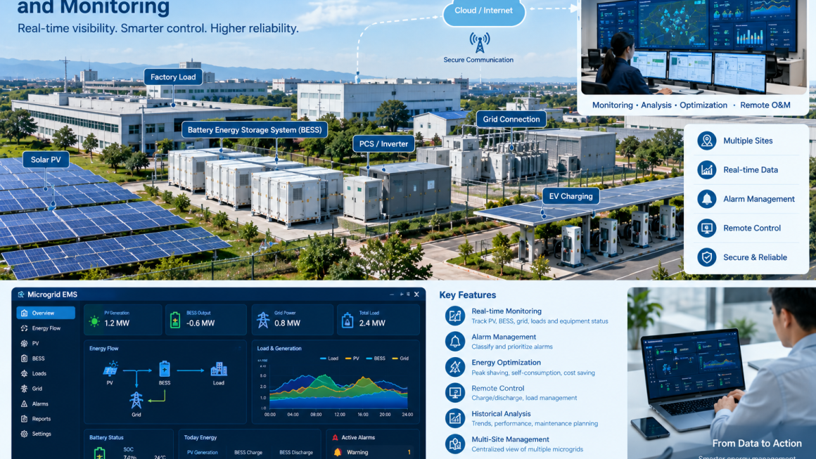
A remote Energy Management System (EMS) provides a digital layer that connects these assets, collects operational data, analyzes system conditions, and coordinates energy flows.
The basic architecture is:
Distributed Energy Assets → Local Controllers → Communication Network → Remote EMS → Monitoring & Optimization
The objective is not simply to see whether equipment is running.
A properly designed remote EMS should help operators understand what is happening, why it is happening, and what action may be required.
What Is a Remote Microgrid EMS?
A remote microgrid EMS is a software and control platform used to monitor and coordinate distributed energy resources from a centralized or cloud-connected interface.
Depending on the system architecture, it can collect information from:
- PV inverters
- BESS
- PCS
- BMS
- Smart meters
- Protection devices
- EV chargers
- Generators
- HVAC systems
- Building management systems
The EMS can then provide:
Real-time monitoring → Data analysis → Alarm management → Energy optimization → Remote control
For multi-site operators, the same platform may monitor several microgrids from one control center.
Why Remote Monitoring Matters
Traditional energy systems often rely heavily on local operators.
An operator may need to physically inspect:
- Battery cabinets
- Inverters
- Distribution equipment
- PV systems
- Cooling equipment
- Communication devices
This becomes inefficient when assets are distributed across a large campus or multiple sites.
Remote monitoring changes the operating model.
Instead of:
Alarm → Wait for site visit → Inspect equipment → Diagnose problem
the workflow can become:
Alarm → Remote diagnosis → Identify affected equipment → Determine response → Dispatch technician if required
This can reduce unnecessary site visits and improve response efficiency.
The Basic Remote EMS Architecture
A practical remote microgrid EMS can be divided into several layers.
Layer 1: Energy Assets
This includes the physical equipment:
- PV
- BESS
- PCS
- Grid connection
- Generator
- Loads
- EV chargers
Layer 2: Local Controllers
Local controllers collect equipment data and execute immediate control functions.
Examples include:
- BMS
- PCS controller
- PV inverter controller
- PLC
- Building controller
Layer 3: Communication Layer
The communication network transfers data between local equipment and the EMS.
Possible technologies include:
- Ethernet
- Fiber optic communication
- Industrial networks
- Cellular communication
- VPN connections
- Other secure IP-based networks
Layer 4: EMS Platform
The EMS aggregates information from different assets.
It can provide:
- Visualization
- Data storage
- Analytics
- Alarm management
- Scheduling
- Optimization
- Remote control
Layer 5: Operator Interface
Operators access the system through:
- Web dashboards
- Control-room displays
- Remote computers
- Mobile interfaces
The result is a hierarchical architecture:
Equipment → Local Control → Communication → EMS → Operator
Real-Time Monitoring: What Should Be Measured?
A remote EMS is only as useful as the data it receives.
Important measurements include:
Grid
- Voltage
- Current
- Frequency
- Active power
- Reactive power
- Power factor
- Import/export energy
PV
- PV power
- Daily generation
- Inverter status
- DC voltage
- AC output
- Production trends
Battery
- State of charge (SOC)
- State of health (SOH)
- Voltage
- Current
- Temperature
- Charge/discharge power
- Alarm status
PCS
- Active power
- Reactive power
- Operating mode
- Conversion status
- Fault status
Loads
- Building demand
- Production load
- HVAC load
- EV charging
- Critical-load status
The EMS can transform these individual measurements into a complete picture of the microgrid.
From Data Collection to Energy Intelligence
Monitoring alone is not the same as energy management.
A dashboard showing hundreds of measurements may provide information but still leave operators asking:
What should I do with this information?
The EMS should convert raw data into useful operational information.
For example:
Grid demand increasing
↓
PV output decreasing
↓
Battery SOC = 72%
↓
Peak-demand threshold approaching
↓
EMS recommends or executes BESS discharge
This transforms the system from passive monitoring into active energy management.
Microgrid Energy Flow Visualization
A useful EMS dashboard should make energy flows easy to understand.
For example:
PV → Building Load
PV → BESS
Grid → Building Load
Grid → BESS
BESS → Building Load
Generator → Microgrid
The operator should be able to see the direction and magnitude of these flows in near real time.
This is particularly useful when multiple energy sources operate simultaneously.
Remote Alarm Management
Alarm management is one of the most valuable functions of a remote EMS.
However, simply displaying every alarm can create another problem:
Alarm overload.
A large microgrid may generate many warnings.
A practical alarm system should distinguish between:
Critical Alarms
Immediate attention may be required.
Examples:
- Major battery fault
- Fire detection
- Critical PCS fault
- Protection trip
- Communication failure affecting critical control
Warning Alarms
The equipment remains operational but should be inspected.
Examples:
- Elevated temperature
- Abnormal voltage
- Reduced cooling performance
- Communication instability
Information Events
These describe normal system changes.
Examples:
- Battery charging started
- Battery discharge completed
- PV output reduced
- Scheduled operating mode changed
This hierarchy helps operators focus on meaningful events.
Remote Fault Diagnosis
Remote EMS platforms can significantly improve troubleshooting.
Suppose a BESS stops discharging.
A simple alarm may say:
BESS discharge unavailable
This is not enough information.
A more useful system can provide the sequence:
Discharge command issued
↓
PCS received command
↓
PCS operating normally
↓
Battery discharge permission unavailable
↓
BMS protection active
↓
Battery temperature above operating threshold
This allows the operator to identify the likely source of the problem without immediately sending a technician to the site.
Data Logging and Historical Analysis
Real-time monitoring answers:
What is happening now?
Historical data answers:
What has been happening over time?
A remote EMS should retain historical information such as:
- Daily energy production
- Battery cycling
- Peak demand
- PV utilization
- Grid consumption
- Alarm history
- Temperature trends
- Equipment availability
Operators can then compare:
Today vs. yesterday
This month vs. previous month
Current season vs. previous season
This can reveal performance degradation or abnormal operating patterns.
Battery Performance Monitoring
Battery storage requires particularly careful monitoring.
Important parameters include:
SOC
Indicates available stored energy.
SOH
Provides an indication of battery condition and remaining performance capability.
Temperature
Helps identify thermal abnormalities.
Voltage
Cell and module voltage trends can reveal imbalance or abnormal conditions.
Charge/Discharge History
Shows how frequently and deeply the battery is being cycled.
A remote EMS can combine these measurements to provide a more complete picture of BESS health.
Remote EMS and Peak Demand Management
The EMS can coordinate battery storage with the site’s demand threshold.
For example:
Normal demand
→ BESS remains available
Demand approaching threshold
→ EMS prepares storage
Demand exceeds target
→ BESS discharges
Demand decreases
→ BESS reduces discharge
This can be combined with flexible loads.
For example:
Grid demand rises
↓
EV charging reduced
HVAC adjusted
BESS discharged
↓
Campus demand stabilized
This multi-resource strategy can reduce dependence on battery storage alone.
PV + Storage Coordination
Remote EMS integration becomes particularly useful when PV and BESS operate together.
During high solar production:
PV output ↑
↓
Building consumption satisfied
↓
Excess PV available
↓
BESS charging
Later:
PV output ↓
↓
Building demand ↑
↓
BESS discharge
The EMS can coordinate these transitions automatically according to system priorities.
Remote Control: What Should Be Controlled?
Remote control should be carefully designed.
Possible commands include:
- BESS charge
- BESS discharge
- Charge/discharge power limit
- Operating mode
- PV curtailment
- Generator start/stop
- EV charging schedule
- Load-control commands
However, remote control should not mean unrestricted control.
Safety-critical functions should remain under local protection systems.
A useful principle is:
Local protection first → Local control second → Remote optimization third
If communication with the remote EMS is lost, the local equipment should still be capable of entering a predefined safe operating mode.
Communication Reliability Is Critical
A remote EMS depends on communication.
Possible failure points include:
- Network interruption
- Cellular signal loss
- Fiber failure
- Gateway failure
- Protocol mismatch
- Device communication timeout
- Server connection failure
Therefore, the system should define what happens when communication is lost.
For example:
Communication lost
↓
Local controller detects timeout
↓
Remote commands disabled
↓
Equipment switches to predefined local strategy
↓
Safety and protection remain active
↓
Communication restored
↓
System resynchronizes
This prevents a communication problem from becoming an energy-system safety problem.
Protocol and Data Integration
A microgrid may contain equipment from multiple manufacturers.
The EMS therefore needs to integrate different devices and data formats.
Typical integration requirements may include:
- Device identification
- Measurement mapping
- Command mapping
- Alarm mapping
- Timestamp synchronization
- Data quality checks
- Communication status
A standardized communication architecture can reduce integration complexity.
The important principle is:
The EMS should integrate the energy system rather than become locked to one equipment supplier.
Cybersecurity for Remote EMS
Remote access creates additional cybersecurity requirements.
A connected microgrid should consider:
- User authentication
- Role-based access
- Secure communication
- Network segmentation
- VPN or equivalent secure access
- Access logging
- Software updates
- Password management
- Backup and recovery
Not every user should have the same level of control.
For example:
Operator
Can monitor equipment and acknowledge alarms.
Engineer
Can modify selected operating parameters.
Administrator
Can manage users and system configuration.
Service Technician
Can access maintenance functions under controlled permissions.
This reduces the risk of accidental or unauthorized changes.
Remote O&M Workflow
A strong EMS can support a more efficient maintenance workflow.
The process can be:
Monitor
↓
Detect abnormal condition
↓
Classify alarm
↓
Remote diagnosis
↓
Determine urgency
↓
Check historical data
↓
Prepare maintenance action
↓
Dispatch technician if necessary
↓
Verify repair remotely
This is especially useful for distributed BESS and microgrid projects where physical access requires significant travel.
Predictive Maintenance
Historical EMS data can also support predictive maintenance.
For example, suppose the system detects:
Cooling fan temperature trend ↑
Battery temperature gradually ↑
Cooling performance ↓
Instead of waiting for a thermal alarm, the operator can schedule inspection earlier.
Similarly:
Communication errors ↑
may indicate a developing network problem.
And:
PCS efficiency ↓
over time may justify technical inspection.
The principle is:
Trend detection → Early warning → Planned maintenance → Reduced unexpected downtime
Multi-Site Microgrid Monitoring
Remote EMS becomes particularly valuable when an operator manages multiple sites.
For example:
Site A — Industrial Park
Site B — Manufacturing Plant
Site C — Commercial Campus
Site D — Remote Energy Storage Site
A centralized platform can provide:
Portfolio overview → Site selection → Equipment detail → Alarm → Historical analysis
Operators can identify which sites require attention without manually checking every location.
This creates a scalable O&M model.
EMS Dashboard Design
A useful dashboard should prioritize information rather than simply display everything.
A practical home screen may show:
System Status
- Online/offline
- Current operating mode
- Active alarms
Energy Flow
- PV power
- BESS power
- Grid power
- Load power
Battery
- SOC
- SOH
- Temperature
- Available power
Performance
- Daily PV generation
- BESS charge/discharge
- Peak demand
- Renewable-energy utilization
Maintenance
- Active warnings
- Communication faults
- Equipment requiring inspection
The goal is:
See the problem quickly → understand the problem quickly → respond appropriately.
Remote EMS for Modular Microgrids
Modularity introduces another advantage.
A microgrid can begin with:
PV + 500 kW BESS
Then expand to:
PV + 1 MW BESS + EV charging
Then:
PV + 2 MW BESS + EV + thermal loads + backup generation
The EMS should expand along with the physical system.
This requires:
- Scalable device management
- Expandable data architecture
- Flexible control logic
- Additional site support
- Modular communication interfaces
The digital architecture should therefore be designed for future expansion just like the physical BESS architecture.
Common Remote EMS Integration Problems
1. Too Much Data, Too Little Information
Collecting thousands of parameters does not automatically create useful intelligence.
Solution: prioritize operationally relevant information.
2. Poor Device Integration
Different equipment suppliers may use different data structures.
Solution: establish an integration and data-mapping strategy early.
3. Remote Control Without Local Fallback
Communication failure can create operational uncertainty.
Solution: maintain independent local control and protection.
4. Excessive Alarms
Too many low-value alarms can hide important events.
Solution: use alarm priorities and event filtering.
5. No Historical Data Strategy
Without historical data, trend analysis becomes difficult.
Solution: define data retention and analysis requirements before commissioning.
6. Insufficient Cybersecurity
Remote access increases the attack surface.
Solution: use secure authentication, network controls, access management, and monitoring.
Best Practices for Remote Microgrid EMS Integration
A practical implementation should follow several principles.
1. Define the Energy Objectives First
Determine whether the primary goals are:
- Peak shaving
- PV self-consumption
- Energy arbitrage
- Backup
- Demand management
- Microgrid resilience
2. Design the Data Architecture Early
Determine:
- What needs to be measured
- How frequently data is collected
- Which devices require control
- How data is stored
3. Separate Safety From Optimization
Safety functions should remain independent from remote optimization commands.
4. Maintain Local Control
A microgrid should continue operating safely when remote communication is unavailable.
5. Prioritize Alarms
Operators should immediately understand the difference between critical faults and routine events.
6. Use Historical Data
Do not limit the EMS to real-time dashboards.
Historical data provides the foundation for:
- Performance analysis
- Fault diagnosis
- Predictive maintenance
- Energy optimization
7. Design for Expansion
The EMS should support additional:
- BESS units
- PV systems
- Buildings
- EV chargers
- Loads
- Microgrid sites
A Practical Remote EMS Operating Model
The complete architecture can be summarized as:
PV + BESS + Grid + Loads
↓
Local Controllers
↓
Secure Communication Network
↓
Remote EMS Platform
↓
Real-Time Monitoring
↓
Alarm & Event Management
↓
Energy Optimization
↓
Remote O&M
↓
Performance Analysis
This creates a continuous operating loop:
Monitor → Analyze → Optimize → Control → Verify → Improve
Conclusion
Remote EMS integration is becoming an important part of modern microgrid infrastructure.
As energy systems become more distributed, operators need more than local equipment displays. They need a coordinated view of PV generation, battery storage, grid demand, flexible loads, and equipment status.
A well-designed remote EMS provides this digital layer.
The most important principles are:
- Collect meaningful real-time data
- Integrate different energy assets
- Coordinate PV, BESS, and loads
- Provide clear alarm prioritization
- Maintain local control and protection
- Support secure remote access
- Use historical data for diagnosis and optimization
- Enable remote O&M
- Design the platform for future expansion
The architecture can be summarized as:
Distributed energy assets → Local control → Secure communication → Remote EMS → Monitoring → Optimization → O&M
The future microgrid is therefore not only a physical combination of batteries, PV systems, electrical equipment, and loads.
It is a connected energy infrastructure in which physical assets and digital management operate together.
For industrial parks, commercial campuses, remote sites, and distributed energy projects, this combination of modular hardware + remote EMS + data-driven O&M can provide a scalable foundation for long-term energy management.
Frequently Asked Questions
What is a remote microgrid EMS?
A remote microgrid EMS is a digital platform that monitors and coordinates distributed energy resources such as PV, BESS, grid connections, generators, and flexible loads from a centralized or remote interface.
What can a remote EMS monitor?
It can monitor grid power, PV output, battery SOC and temperature, PCS status, building loads, alarms, communication status, and other operational parameters.
Can an EMS control a BESS remotely?
Yes, depending on the system architecture and permissions. Remote commands can include charging, discharging, power limits, and operating modes. Safety-critical protection should remain locally controlled.
What happens if communication with the EMS is lost?
A properly designed system should have a local fallback strategy. Local controllers and protection systems can continue operating according to predefined rules while remote communication is unavailable.
Why is historical data important?
Historical data allows operators to identify trends, investigate faults, compare system performance, and support predictive maintenance.
Can one EMS monitor multiple microgrids?
Yes. A scalable remote EMS can provide centralized monitoring and management for multiple distributed microgrid sites.
How does remote EMS support O&M?
It can identify alarms, provide equipment status, support remote diagnosis, track historical performance, and help maintenance teams determine whether an on-site visit is required.
Is cybersecurity important for remote microgrid monitoring?
Yes. Remote connectivity should be designed with appropriate authentication, access control, secure communication, network protection, logging, and recovery procedures.
Can a remote EMS support future microgrid expansion?
Yes. The EMS architecture should be designed to accommodate additional BESS units, PV systems, buildings, EV chargers, flexible loads, and additional sites as the microgrid expands.