



As AI servers and high-performance computing systems continue to increase in power density, conventional air cooling is becoming increasingly difficult to use as the primary thermal-management method.
Modern GPU and CPU platforms can generate substantial heat within a relatively small physical area. Removing this heat efficiently requires a cooling architecture that can bring the coolant much closer to the heat source.
Direct-to-Chip (D2C) liquid cooling addresses this challenge by circulating liquid directly through cold plates mounted on high-heat-generating components such as GPUs, CPUs, and other processors.
However, the cold plate itself is only one part of the system.
A reliable D2C cooling loop also depends on:
- Coolant distribution
- Manifolds
- Hoses and tubing
- Quick disconnect couplings
- Sealing systems
- Pumps
- Heat exchangers
- Flow monitoring
- Leak detection
- Serviceability
Among these components, quick disconnect couplings (QDs) play a particularly important role.
They allow liquid-cooling circuits to be connected and disconnected during server installation, maintenance, rack replacement, and component servicing.
The challenge is that every additional connection in a liquid loop creates another potential source of leakage, pressure loss, mechanical stress, and contamination.
Therefore, successful D2C liquid cooling requires a system-level approach.
1. What Is Direct-to-Chip Liquid Cooling?
Direct-to-Chip cooling places a liquid-cooled cold plate directly on the processor or other high-power component.
A simplified thermal path is:
GPU / CPU → Thermal Interface Material → Cold Plate → Coolant → Manifold → CDU / Heat Exchanger
Instead of relying primarily on air to carry heat away from the chip, liquid transports the heat through the cooling loop.
Because liquids generally have much higher volumetric heat capacity than air, liquid cooling can move substantial amounts of heat through relatively compact flow paths.
This makes D2C particularly attractive for:
- AI servers
- GPU clusters
- HPC systems
- High-density data centers
- Scientific computing
- High-performance networking equipment
2. Why D2C Systems Need Quick Disconnects
A data center cannot treat an entire cooling loop as a permanent installation.
Servers eventually need to be:
- Installed
- Removed
- Upgraded
- Repaired
- Reconfigured
- Replaced
If cooling connections cannot be disconnected safely, even a relatively simple server replacement can require draining part of the cooling loop.
This can increase:
- Maintenance time
- Coolant loss
- Contamination risk
- Downtime
- Service complexity
Quick disconnect couplings provide a practical interface between fixed and removable portions of the cooling loop.
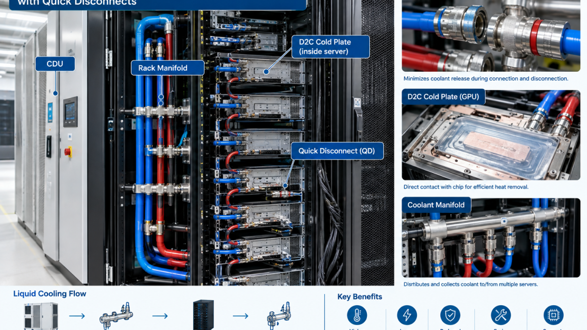
A typical architecture may look like:
CDU
↓
Rack Manifold
↓
QD
↓
Server Supply Line
↓
Cold Plate
↓
Server Return Line
↓
QD
↓
Rack Manifold
This creates a serviceable interface without requiring the entire cooling infrastructure to be dismantled.
3. The Basic D2C Cooling Loop
A typical liquid-cooling architecture can include several levels.
Facility side
- Facility water loop
- Cooling tower
- Dry cooler
- Chiller
- Heat exchanger
CDU side
- Pump
- Heat exchanger
- Filters
- Expansion components
- Controls
- Monitoring
Rack side
- Supply manifold
- Return manifold
- Flow control
- Temperature sensors
- Pressure sensors
Server side
- Quick disconnects
- Hoses
- Cold plates
- Internal distribution channels
The system therefore contains multiple interfaces.
Every interface should be evaluated for:
Flow + pressure + temperature + sealing + serviceability
4. QD Selection Should Start with System Requirements
Choosing a quick disconnect based only on nominal port size is not sufficient.
Important parameters include:
- Required flow rate
- Operating pressure
- Pressure drop
- Coolant type
- Operating temperature
- Connection size
- Materials
- Seal materials
- Connection/disconnection frequency
- Leakage tolerance
- Space constraints
- Service requirements
For example, a QD that performs well in a low-flow laboratory cooling system may not be appropriate for a high-density AI server rack.
The correct question is:
Does the QD meet the requirements of the complete cooling loop?
5. Flow Rate Is a Fundamental Design Parameter
The amount of heat that can be removed by the coolant depends strongly on coolant flow rate and temperature rise.
A simplified relationship is:
Q = ṁ × Cp × ΔT
Where:
- Q = heat removed
- ṁ = coolant mass flow rate
- Cp = specific heat capacity
- ΔT = coolant temperature difference between supply and return
Increasing flow can increase heat-removal capability, but it also affects:
- Pump power
- Pressure drop
- QD pressure loss
- Hose diameter
- Manifold design
Therefore, simply increasing flow is not always the best solution.
The entire hydraulic system needs to be balanced.
6. Pressure Drop Through Quick Disconnects Matters
Every QD introduces some hydraulic resistance.
If the pressure drop is too high, the system may require additional pump power to maintain the desired flow.
The overall pressure drop can be viewed as:
Total ΔP = QD ΔP + Hose ΔP + Manifold ΔP + Cold Plate ΔP + Other ΔP
A QD with a small internal flow passage may create significant pressure loss at high flow rates.
Therefore, QD selection should consider the complete pressure-drop curve rather than simply the connection diameter.
Best practice
Compare candidate QDs at the actual expected operating flow rate.
A component that looks efficient at low flow may behave very differently at higher flow.
7. Flow Distribution Across Multiple GPUs
High-density AI servers may contain multiple GPUs or processors connected to a common cooling loop.
This introduces a flow-balancing problem.
For example:
Manifold
↓
GPU 1
GPU 2
GPU 3
GPU 4
If hydraulic resistance differs significantly between branches, some cold plates may receive more coolant than others.
This can create:
Uneven flow → uneven thermal performance → different component temperatures
A good D2C design therefore considers:
- Manifold geometry
- Branch resistance
- Cold-plate resistance
- Hose length
- QD pressure drop
- Flow-control devices
QD selection can therefore affect the overall hydraulic balance.
8. Minimize Restriction Without Sacrificing Sealing
There is always a design trade-off between flow performance and mechanical requirements.
A larger internal flow passage can reduce pressure drop.
However, QDs must also provide:
- Reliable shutoff
- Mechanical strength
- Compact dimensions
- Leak resistance
- Connection security
The goal is not simply:
Maximum internal diameter
but:
Optimal hydraulic performance within the required mechanical envelope.
This is especially important in densely packed server environments where space is limited.
9. Dry-Break QDs Are Important for Serviceability
A major concern with liquid-cooled servers is coolant leakage during disconnection.
A conventional coupling may allow some residual fluid to escape.
A dry-break quick disconnect is designed to minimize fluid loss when the connection is separated.
This can provide several benefits:
- Reduced coolant loss
- Cleaner maintenance
- Lower contamination risk
- Less cleanup
- Easier server replacement
For data-center environments, minimizing coolant release is particularly important because liquid and sensitive electronic equipment must coexist within a tightly controlled physical environment.
10. Leakage Prevention Requires More Than the QD
A reliable liquid-cooling system cannot depend on the QD alone.
Leak prevention requires coordination between:
- QD
- Hose
- Fitting
- Seal
- Cold plate
- Manifold
- Connection geometry
Potential failure mechanisms include:
- Seal degradation
- Incorrect assembly
- Mechanical overloading
- Excessive bending
- Thermal cycling
- Vibration
- Contamination
- Improper mating
Therefore:
Leak prevention = component design + installation quality + maintenance practice
11. Seal Material Must Match the Coolant
Seal compatibility is an important but sometimes overlooked factor.
Different liquid-cooling systems may use:
- Water
- Water/glycol mixtures
- Dielectric fluids
- Proprietary coolants
Seal materials should be evaluated for:
- Chemical compatibility
- Temperature resistance
- Swelling
- Compression set
- Long-term aging
A seal that performs well with one coolant may not have the same lifetime with another.
Material compatibility should therefore be verified for the actual coolant chemistry and operating temperature.
12. Coolant Cleanliness Is Critical
Small particles can affect liquid-cooling components.
Contamination can potentially cause:
- Valve problems
- Seal damage
- Flow restriction
- Cold-plate fouling
- Filter loading
This is especially important for small internal flow passages.
A complete system should therefore consider:
- Filtration
- Coolant cleanliness
- Flushing procedures
- Particle control
- Maintenance intervals
When QDs are repeatedly connected and disconnected, contamination control becomes even more important.
The connection area should be kept clean during service.
13. QD Orientation and Installation Matter
Quick disconnects should not be installed under unnecessary mechanical stress.
Hoses should have sufficient flexibility to accommodate:
- Server insertion
- Server removal
- Thermal expansion
- Equipment vibration
- Minor movement
Excessive hose bending near the QD can create mechanical loads on the connection.
A better arrangement is:
QD → short flexible section → supported hose
rather than forcing a rigid hose to bend immediately at the coupling.
This can reduce stress on both the QD and its mating connection.
14. Avoid Side Loading
A QD is designed primarily to manage hydraulic and axial connection loads.
It should not be treated as a structural support point.
Side loading can occur when:
- Hoses are too short
- Hoses are poorly routed
- Server movement pulls on the connection
- Heavy hoses are unsupported
This can accelerate seal wear and potentially damage fittings.
Proper hose support and routing should therefore be part of the mechanical design.
15. Thermal Expansion Must Be Considered
Liquid-cooling components operate across temperature ranges.
As the coolant heats and cools:
Temperature changes → material expansion/contraction
Different materials may expand at different rates.
This can create mechanical stress at:
- QD connections
- Fittings
- Manifolds
- Cold plates
- Rigid tubing
Flexible sections can help accommodate this movement.
The cooling loop should therefore be designed so that normal thermal cycling does not continuously load the connection points.
16. Temperature and Pressure Monitoring
A D2C cooling system should provide sufficient monitoring to detect abnormal operating conditions.
Important parameters include:
- Supply temperature
- Return temperature
- Flow rate
- Differential pressure
- Pump status
- Coolant level
- Leak detection
For example:
Return temperature increases
↓
Possible reduction in cooling performance
↓
Check flow rate
↓
Check pressure drop
↓
Inspect filter / QD / cold plate
This provides a practical troubleshooting pathway.
17. Leak Detection Should Be Integrated
Even the best QD cannot guarantee zero leakage under every possible failure condition.
Leak detection can provide an additional protection layer.
Potential technologies include:
- Leak detection cables
- Point sensors
- Conductivity sensors
- Pressure monitoring
- Flow imbalance detection
A sudden change in:
Flow + pressure + coolant level
may indicate a problem.
The system can then trigger an alarm or controlled shutdown.
18. QD Reliability Should Be Evaluated Over Repeated Cycles
A QD may work perfectly during its first connection.
The more important question for service applications is:
How does it perform after repeated mating and unmating cycles?
Repeated servicing can gradually affect:
- Seals
- Locking mechanisms
- Internal valves
- Surface finishes
- Connection force
Therefore, the required number of connection cycles should be part of the specification.
For frequently serviced AI servers, cycle durability can be an important selection criterion.
19. Connection Force and Ergonomics Matter
A technically excellent QD can still be inconvenient if technicians struggle to connect or disconnect it.
Operators may need to work in:
- Narrow rack spaces
- Dense server environments
- Limited-access areas
The QD should therefore provide:
- Clear locking feedback
- Appropriate connection force
- Easy identification
- Good hand access
- Secure locking
- Simple service procedure
Serviceability is part of reliability.
If a component is difficult to service correctly, maintenance errors become more likely.
20. Color Coding and Identification Can Reduce Errors
Liquid-cooling systems may contain multiple connections.
Clear identification can reduce installation mistakes.
Possible approaches include:
- Supply / return labels
- Color coding
- Flow-direction markings
- Port numbering
- Connection tags
For example:
SUPPLY → Server
RETURN → Manifold
This is particularly useful when multiple servers are being installed or serviced simultaneously.
21. Prevent Cross-Connection Between Supply and Return
Incorrect connection can lead to poor thermal performance or unexpected flow behavior.
The system should therefore make incorrect connection difficult.
Design approaches may include:
- Different QD sizes
- Different connection keys
- Clear labeling
- Color coding
- Dedicated port geometry
This follows a broader engineering principle:
Good design should prevent mistakes rather than rely entirely on operator memory.
22. Maintenance Procedures Should Minimize Coolant Exposure
A practical server replacement sequence may be:
1. Stop or isolate the server
↓
2. Confirm cooling loop status
↓
3. Close or isolate the relevant flow path
↓
4. Disconnect QDs
↓
5. Remove the server
↓
6. Install replacement server
↓
7. Reconnect QDs
↓
8. Verify locking
↓
9. Check for leaks
↓
10. Confirm flow and temperature
↓
11. Return server to operation
The exact procedure depends on system architecture, but the key principle is consistent:
Maintenance should be designed into the cooling system from the beginning.
23. QD Selection Should Consider the Entire Lifecycle
The cheapest QD is not necessarily the lowest-cost option.
Lifecycle cost can include:
- Initial purchase
- Installation
- Coolant loss
- Maintenance
- Replacement
- Downtime
- Leak-related incidents
- Technician labor
A higher-quality coupling may have a higher initial cost but lower lifecycle risk.
For high-density computing infrastructure, avoiding one significant cooling failure can easily outweigh the initial price difference between components.
24. D2C Cooling Should Be Designed as a Complete Hydraulic System
One of the most important best practices is to avoid selecting components independently.
The cold plate, QD, hose, manifold, pump, heat exchanger, and coolant should be evaluated together.
For example:
High-performance cold plate
High-flow QD
Large-diameter hose
may still perform poorly if:
Manifold restriction is excessive
or:
Pump capacity is insufficient
System-level pressure and flow analysis is therefore essential.
25. D2C Cooling and Aluminum Components
Aluminum can be an attractive material for various liquid-cooling components because of its:
- Low density
- Thermal conductivity
- Manufacturability
- Extrusion capability
- Machinability
Potential applications include:
- Cold plates
- Manifolds
- Structural cooling components
- Heat exchangers
- Mounting structures
However, material selection must consider the complete coolant environment.
Important factors include:
- Corrosion compatibility
- Coolant chemistry
- Galvanic corrosion
- Surface treatment
- Joining methods
When aluminum is combined with copper, stainless steel, brass, or other metals, galvanic compatibility should be evaluated carefully.
26. The Role of Quick Disconnects in Rack-Level Modularity
As AI infrastructure becomes increasingly modular, QDs can become an important interface technology.
A rack can be designed as:
Facility cooling
↓
CDU
↓
Rack manifold
↓
QD interface
↓
Server modules
This allows servers to be replaced without redesigning the entire cooling infrastructure.
The same concept supports:
- Rack upgrades
- GPU replacements
- Server maintenance
- Capacity expansion
- Modular deployment
This is particularly valuable as computing hardware evolves rapidly.
27. Best-Practice Checklist
Before approving a D2C liquid-cooling QD design, engineers should verify:
Hydraulic
- Required flow rate
- Pressure drop
- Flow balancing
- Pump capacity
- Manifold compatibility
Mechanical
- Connection dimensions
- Hose flexibility
- Side-load resistance
- Thermal expansion
- Mounting support
Sealing
- Coolant compatibility
- Temperature range
- Pressure rating
- Seal life
- Leakage performance
Serviceability
- Connection force
- Locking mechanism
- Connection cycle life
- Access space
- Supply/return identification
Reliability
- Vibration
- Thermal cycling
- Corrosion
- Contamination
- Long-term aging
Monitoring
- Flow
- Pressure
- Temperature
- Leak detection
- Alarm integration
A QD should be evaluated as part of the entire cooling system rather than as an isolated fitting.
28. Future Trends in D2C Liquid Cooling
As AI and HPC power density continues to increase, liquid cooling architectures are likely to become more sophisticated.
Future systems may increasingly incorporate:
- Higher-flow cold plates
- Advanced manifold designs
- Lower-pressure-drop QDs
- Automated leak detection
- Smart flow control
- Digital thermal monitoring
- More modular rack interfaces
- Higher-temperature coolant operation
- Improved coolant chemistry
The role of QDs may also expand from simple mechanical connectors into highly engineered service interfaces.
Their performance will directly affect:
Thermal efficiency + serviceability + reliability
Direct-to-Chip liquid cooling provides an effective approach for managing the increasing thermal density of AI servers and HPC systems.
But the performance of a D2C system depends on much more than the cold plate.
Quick disconnects, hoses, manifolds, pumps, coolant, seals, monitoring, and maintenance procedures must work together as one hydraulic system.
The most important best practices include:
- Select QDs based on actual flow and pressure requirements
- Minimize unnecessary pressure drop
- Use appropriate dry-break technology where coolant release must be minimized
- Verify seal and coolant compatibility
- Control contamination
- Prevent hose side loading
- Accommodate thermal expansion
- Monitor flow, temperature, and pressure
- Integrate leak detection
- Design for repeated service cycles
- Make supply and return connections easy to identify
- Evaluate total lifecycle cost
Ultimately, a good D2C cooling system should not only remove heat efficiently.
It should also be safe to service, easy to scale, resistant to leakage, and reliable over thousands of operating and maintenance cycles.
As AI data centers move toward higher rack power densities, these details will increasingly determine whether liquid cooling infrastructure performs reliably at scale.
Frequently Asked Questions
What is Direct-to-Chip liquid cooling?
D2C liquid cooling circulates coolant through cold plates directly attached to high-heat-generating components such as CPUs and GPUs.
Why are quick disconnects used in D2C cooling?
QDs allow liquid-cooled servers and other modules to be connected and disconnected without requiring the entire cooling loop to be drained.
What is a dry-break quick disconnect?
A dry-break QD is designed to minimize coolant release when the connection is disconnected, making it useful for maintenance-intensive liquid-cooling systems.
How does a QD affect cooling performance?
A QD introduces hydraulic resistance. Excessive pressure drop can reduce flow or increase pump power requirements, so QD pressure-drop performance should be evaluated at the actual operating flow rate.
What should be considered when selecting a D2C QD?
Key factors include flow rate, pressure drop, operating pressure, temperature, coolant compatibility, seal material, connection cycle life, leakage performance, dimensions, and serviceability.
Why is coolant compatibility important?
The coolant can interact with seals and wetted materials. Incompatible combinations may cause swelling, degradation, corrosion, or premature failure.
How can liquid-cooling leaks be reduced?
Leak prevention requires compatible seals, proper QD selection, correct hose routing, controlled assembly, contamination management, thermal-expansion accommodation, and leak monitoring.
Can aluminum be used in D2C liquid cooling?
Yes. Aluminum can be used for cold plates, manifolds, heat exchangers, and other components, but coolant chemistry, surface treatment, and galvanic compatibility with other metals must be evaluated.
How often should QDs be replaced?
There is no universal replacement interval. Service frequency, connection cycles, coolant conditions, seal life, operating temperature, and manufacturer specifications should determine inspection and replacement requirements.
Why is QD design important for AI data centers?
As AI racks become more power-dense and more frequently serviced or upgraded, QDs become critical interfaces between the permanent cooling infrastructure and removable computing hardware. Their hydraulic performance and reliability directly influence cooling efficiency and serviceability.