

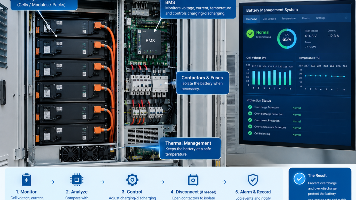
Battery energy storage systems depend on a Battery Management System (BMS) to monitor and control battery operation.
Among its most important safety functions are preventing overcharge and over-discharge.
If a battery is charged beyond its allowable voltage range, or discharged below its safe voltage limit, battery performance, service life, and safety can be affected.
But how does a BMS actually prevent these conditions?
The answer involves continuous voltage and current monitoring, predefined protection thresholds, control commands, contactors, alarms, and multiple layers of protection.
This article explains how a BMS detects and responds to overcharge and over-discharge conditions in battery energy storage systems.
What Is a BMS?
A Battery Management System is an electronic control and monitoring system designed to supervise the operating condition of a battery system.
Depending on the battery architecture, a BMS may monitor:
- Cell voltage
- Pack voltage
- Charging current
- Discharging current
- Cell temperature
- Battery temperature
- State of Charge (SOC)
- State of Health (SOH)
- Cell imbalance
- Insulation or isolation status
- Fault conditions
The BMS uses this information to determine whether the battery is operating within its permitted limits.
It can then communicate with other system components such as:
- PCS
- Hybrid inverter
- Energy management system
- Charging equipment
- Monitoring platform
- Battery contactors
The BMS is therefore an important control layer between the battery and the rest of the energy system.
What Is Battery Overcharge?
Overcharge occurs when a battery cell is charged beyond its specified safe operating voltage.
For lithium-ion batteries, the allowable voltage depends on the specific chemistry and cell design.
The problem is that battery voltage is not simply a fixed value.
It changes according to:
- SOC
- Temperature
- Charging current
- Cell characteristics
- Aging
- Internal resistance
This is why battery protection cannot rely on a simple timer or a fixed charging duration.
The BMS continuously monitors the battery’s electrical condition.
Why Is Overcharge a Problem?
Excessive charging can cause undesirable electrochemical reactions inside a battery cell.
Depending on battery chemistry and severity, overcharge may contribute to:
- Accelerated degradation
- Capacity loss
- Increased internal resistance
- Cell swelling
- Gas generation
- Heat generation
- Internal damage
- Thermal safety risks
The exact failure mechanism depends on the battery chemistry, cell construction, operating conditions, and severity of the overcharge event.
For this reason, preventing overcharge is one of the fundamental functions of a battery management system.
How Does the BMS Detect Overcharge?
The BMS continuously measures individual cell voltages and pack-level electrical parameters.
A simplified protection logic is:
Cell voltage rises toward upper limit
↓
BMS detects high-voltage condition
↓
BMS sends a charge-limit or stop-charge command
↓
Charging current is reduced or stopped
↓
If necessary, protection contactors disconnect the battery
The important point is that the BMS can monitor individual cells, not just the total battery pack voltage.
This is critical because cells connected in series may not remain perfectly balanced.
Why Individual Cell Voltage Matters
Consider a battery pack containing many cells connected in series.
The total pack voltage may appear normal even when one individual cell is approaching its upper voltage limit.
For example:
Cell A → Normal
Cell B → Normal
Cell C → Normal
Cell D → Higher than the others
The average pack voltage may still appear acceptable.
If the BMS monitored only total pack voltage, it could miss the cell-level problem.
Therefore, modern battery management systems typically monitor individual cell voltages or groups of cells, depending on the battery architecture.
What Happens When a Cell Reaches the Upper Voltage Limit?
The response depends on the BMS design and protection settings.
Possible actions include:
1. Reduce Charging Current
The BMS can communicate with the charger or PCS to reduce charging power.
2. Stop Charging
If the voltage reaches a protection threshold, the BMS can request that charging stop.
3. Open the Charging Path
In systems equipped with appropriate contactors, the BMS can initiate disconnection of the battery from the charging circuit.
4. Generate an Alarm
The system can report a high-voltage or overcharge warning to the monitoring platform.
5. Trigger a Fault
If the condition exceeds a more serious protection threshold, the BMS can place the battery system into a fault state.
The exact sequence varies between manufacturers and system architectures.
What Is Over-discharge?
Over-discharge occurs when a battery cell is discharged below its specified minimum operating voltage.
As with overcharge, the important measurement is often the individual cell voltage, not simply the total pack voltage.
A battery can continue delivering power even when one cell is approaching its lower voltage limit.
If discharge continues, that cell may become excessively depleted.
Why Is Over-discharge a Problem?
Excessive discharge can contribute to:
- Capacity degradation
- Increased internal resistance
- Cell imbalance
- Reduced cycle life
- Loss of usable capacity
- Potential cell damage
Severe over-discharge may make a cell difficult or unsafe to recharge, depending on the battery chemistry and the duration of the condition.
The BMS therefore monitors the lowest cell voltage during discharge.
How Does the BMS Prevent Over-discharge?
The basic protection process is similar to overcharge protection.
Cell voltage decreases toward lower limit
↓
BMS detects low-voltage condition
↓
BMS requests discharge power reduction or stop
↓
Load is disconnected or discharge is stopped
↓
Battery enters a protected state
The BMS may also communicate the battery’s available discharge power to the PCS or inverter.
This allows the energy system to reduce output before a hard protection limit is reached.
Protection Usually Uses Multiple Thresholds
A well-designed BMS does not necessarily wait until a dangerous limit is reached before taking action.
Protection can involve different thresholds.
For example:
Normal operating range
↓
Warning threshold
↓
Protection threshold
↓
Critical fault threshold
The exact voltage values and timing depend on the battery chemistry and manufacturer’s specifications.
This layered approach allows the system to respond progressively.
BMS and SOC Estimation
State of Charge (SOC) is another important factor.
SOC estimates how much usable energy remains in the battery.
The BMS may use information such as:
- Voltage
- Current
- Charge/discharge history
- Temperature
- Battery model parameters
to estimate SOC.
When SOC approaches the configured lower operating range, the system can reduce or stop discharge before the battery reaches a damaging condition.
Similarly, when SOC approaches the upper range, charging can be reduced or stopped.
However, SOC should not be treated as a direct substitute for cell-voltage protection.
Voltage-based protection provides a critical physical boundary, while SOC is an operating estimate.
What Is the Role of Cell Balancing?
Cell balancing is closely related to overcharge prevention.
Cells in a battery pack are not perfectly identical.
Over time, differences in:
- Capacity
- Internal resistance
- Temperature
- Aging
- Self-discharge
can cause cells to drift apart in voltage.
For example:
Cell 1: 4.08 V
Cell 2: 4.10 V
Cell 3: 4.15 V
Cell 4: 4.18 V
Even if the overall pack voltage appears acceptable, the highest-voltage cell may approach its upper limit first.
Cell balancing helps reduce this voltage difference.
Passive and Active Cell Balancing
Two common approaches are passive and active balancing.
Passive Balancing
Passive balancing removes a small amount of energy from higher-voltage cells, typically by dissipating it as heat through a balancing circuit.
Advantages may include:
- Simpler architecture
- Lower cost
- Easier implementation
The disadvantage is that balancing energy is dissipated rather than transferred to another cell.
Active Balancing
Active balancing transfers energy between cells or cell groups.
Potential advantages include:
- More efficient energy management
- Reduced energy loss
- Greater balancing capability in some architectures
However, active balancing generally requires more complex electronics and control.
The appropriate method depends on the battery design and application.
BMS and the PCS or Hybrid Inverter
In an energy storage system, the BMS normally does not operate in isolation.
It communicates with the PCS or hybrid inverter.
A simplified control relationship is:
BMS → Battery operating limits → PCS
The BMS may provide information such as:
- Maximum allowable charging current
- Maximum allowable discharging current
- Battery voltage
- SOC
- Temperature
- Alarm status
- Fault status
The PCS uses these limits when controlling power flow.
For example, when the battery approaches its upper SOC or voltage limit, the BMS may reduce the permitted charging current.
When the battery approaches its lower operating limit, the BMS can reduce allowable discharge power.
BMS Protection vs. System-Level Protection
It is important to understand that the BMS is not the only safety mechanism in an energy storage system.
A complete battery system may include multiple protection layers.
These can include:
Cell-Level Protection
Monitoring individual cell voltage and temperature.
BMS Protection
Monitoring battery operating conditions and controlling charging/discharging limits.
Electrical Protection
Fuses, breakers, contactors, and other electrical protection devices.
PCS Protection
The inverter or PCS may have its own voltage, current, temperature, and fault protections.
Thermal Protection
Temperature sensors, cooling systems, thermal monitoring, and other thermal management mechanisms.
System-Level Safety
Emergency shutdown, fire detection, isolation, ventilation, and other safety systems depending on the installation.
This layered approach is important because no single component should be assumed to provide complete protection against every failure mode.
What Happens If Communication With the BMS Is Lost?
This is an important commissioning and O&M question.
If the PCS or inverter can no longer receive reliable information from the BMS, the system should have a defined fail-safe response.
Depending on the system architecture, this may include:
- Limiting charging/discharging
- Stopping power transfer
- Opening contactors
- Generating an alarm
- Entering a fault state
Installers should confirm the manufacturer’s communication-loss strategy rather than assuming that all systems behave identically.
BMS Protection During Charging
A simplified charging sequence may look like:
Battery starts charging
↓
BMS monitors cell voltage and temperature
↓
SOC increases
↓
Highest cell approaches upper limit
↓
BMS reduces allowable charging current
↓
Charging reaches upper operating boundary
↓
Charging stops or battery is disconnected if required
This process allows the battery to approach its usable capacity without unnecessarily exceeding its operating limits.
BMS Protection During Discharging
The discharge sequence is similar:
Battery supplies power
↓
BMS monitors lowest cell voltage
↓
SOC decreases
↓
Lowest cell approaches lower operating limit
↓
BMS reduces allowable discharge current
↓
Discharge stops when the protection boundary is reached
This prevents continued operation below the battery’s specified safe voltage range.
Temperature Also Matters
Voltage protection cannot be considered independently from temperature.
Battery characteristics can change significantly with temperature.
The BMS may therefore monitor:
- Cell temperature
- Module temperature
- Battery pack temperature
- Temperature differences between cells
If the battery becomes too hot or too cold, the BMS may restrict charging or discharging even when voltage remains within normal limits.
For example, a battery may have a narrower allowable charging range at low temperatures depending on its chemistry and design.
Therefore:
Voltage + Current + Temperature + SOC
provide a more complete picture of battery operating conditions.
Why BMS Settings Must Match the Battery Chemistry
Different battery chemistries have different electrical and thermal characteristics.
The BMS protection thresholds must therefore be configured according to the specific battery cells and manufacturer’s requirements.
Installers should not copy voltage limits from another battery system simply because both systems are described as “lithium batteries.”
Important parameters may include:
- Cell chemistry
- Maximum cell voltage
- Minimum cell voltage
- Charging temperature range
- Discharging temperature range
- Maximum charging current
- Maximum discharge current
- Recommended SOC range
Correct BMS configuration is essential for both safety and battery life.
What Installers Should Check
Before commissioning a battery energy storage system, installers should verify:
| Check Item | What to Confirm |
|---|---|
| Cell voltage monitoring | Individual cell monitoring is functioning |
| High-voltage protection | Upper voltage thresholds are configured correctly |
| Low-voltage protection | Lower voltage thresholds are configured correctly |
| Current limits | Charging and discharging limits are correct |
| Temperature | Sensors are correctly installed and reporting |
| Cell balancing | Balancing function operates as specified |
| SOC | SOC reading is reasonable and consistent |
| PCS communication | BMS and PCS communicate correctly |
| Protection response | Charging/discharging limits respond correctly |
| Contactors | Contactors operate according to system logic |
| Alarm system | Warnings and faults are correctly reported |
| Recovery | Recovery procedure after a protection event is documented |
The exact test procedures should follow the battery and BMS manufacturer’s commissioning instructions.
Common Misunderstandings About BMS Protection
“The BMS Stops All Overcharge Problems”
Not necessarily.
The BMS is one important protection layer, but the overall system should also include appropriate electrical, thermal, control, and safety mechanisms.
“Pack Voltage Is Enough”
Not always.
Individual cell voltage can be more important because cell imbalance can cause one cell to reach its limit before the entire pack does.
“SOC = Battery Voltage”
No.
SOC is an estimate of remaining usable energy and should not be treated as a direct replacement for voltage-based protection.
“A Full Battery Is Always at Risk of Overcharge”
Not necessarily.
A properly controlled charging system stops or reduces charging when the battery reaches its configured operating limits.
“BMS Protection Eliminates the Need for O&M”
No.
Physical inspection remains important.
Installers should still inspect:
- Battery connections
- Cable routing
- Connectors
- Cable protection
- Cooling systems
- Enclosures
- Sealing
- Environmental conditions
- Signs of overheating or damage
BMS Protection Is a Layered Process
The simplest way to understand BMS protection is:
Measure → Compare → Communicate → Limit → Disconnect if necessary → Record
The BMS continuously measures battery conditions.
It compares them with configured operating and protection limits.
It communicates allowable operating parameters to the PCS or inverter.
If the battery approaches an operating boundary, the system can reduce charging or discharging power.
If the condition reaches a protection threshold, charging or discharging can be stopped and, where designed for that purpose, the battery can be electrically isolated.
This layered approach helps prevent abnormal battery operation before it develops into a more serious problem.
A BMS prevents battery overcharge and over-discharge by continuously monitoring cell voltage, pack voltage, current, temperature, SOC, and other operating parameters.
For overcharge protection, the BMS monitors the highest cell voltage and can progressively reduce or stop charging when the battery approaches its upper operating limits.
For over-discharge protection, it monitors the lowest cell voltage and can reduce or stop discharge when the battery approaches its lower operating limits.
Cell balancing helps manage differences between cells, while communication with the PCS or hybrid inverter allows battery operating limits to be incorporated into overall power control.
However, BMS protection should always be viewed as part of a layered battery safety and O&M architecture, not as the only protection mechanism.
For installers, the most important questions are therefore not only:
“Does the battery have a BMS?”
but also:
“Does the BMS correctly monitor, communicate, limit, disconnect, alarm, and recover the battery under abnormal operating conditions?”
A properly configured BMS, combined with appropriate electrical protection, thermal management, system controls, and physical O&M, provides a stronger foundation for reliable long-term battery energy storage operation.