

Liquid cooling is becoming increasingly important for high-density computing infrastructure, particularly as AI servers and high-performance processors generate greater heat loads.
In these systems, quick disconnects (QDs) play an important role in connecting and disconnecting coolant lines while allowing equipment to be serviced, replaced, or upgraded with minimal disruption.
QDs may appear to be relatively small components compared with cold plates, manifolds, pumps, or heat exchangers.
However, their reliability is critical.
A damaged or improperly maintained quick disconnect can contribute to:
- Coolant leakage
- Reduced flow
- Pressure loss
- Air ingress
- Contamination
- Difficult servicing
- Unplanned equipment downtime
For this reason, QDs should be treated as maintenance-critical components rather than simple accessories.
A good maintenance strategy combines visual inspection, leak prevention, connection checks, cleanliness control, seal inspection, performance monitoring, and controlled replacement procedures.
What Are Liquid Cooling QDs?
Quick disconnects are mechanical couplings that allow a liquid cooling line to be connected or disconnected without permanently opening or rebuilding the entire piping system.
They can be used in:
- Server liquid-cooling loops
- CDU connections
- Manifold assemblies
- Cold-plate circuits
- Rack-level cooling systems
- Serviceable component connections
Depending on system design, QDs may incorporate shut-off mechanisms that help minimize coolant loss when a connection is disconnected.
Common design considerations include:
- Flow capacity
- Pressure rating
- Temperature range
- Seal material
- Connection size
- Material compatibility
- Connection method
- Leak resistance
The exact design must be matched to the cooling system and coolant chemistry.
Why QD Maintenance Matters
A liquid cooling system can contain many individual connection points.
Each additional connection represents another potential source of:
- Leakage
- Mechanical wear
- Seal degradation
- Contamination
- Flow restriction
As rack density and coolant flow increase, the consequences of a connection failure can become more significant.
A reliable QD maintenance program helps detect problems before they develop into larger cooling-system failures.
The Main QD Failure Modes
Understanding common failure modes makes inspection more effective.
Seal Degradation
O-rings and other seals may deteriorate due to:
- Temperature
- Pressure
- Chemical exposure
- Aging
- Repeated connection cycles
A seal that appears acceptable externally may still have lost elasticity or developed surface damage.
Mechanical Wear
Repeated connection and disconnection can gradually wear:
- Locking mechanisms
- Valves
- Coupling surfaces
- Retaining components
Mechanical wear can eventually make the connection less reliable.
Contamination
Dust, particles, fibers, corrosion products, or other contaminants can enter the coupling.
Contamination may interfere with:
- Sealing
- Valve movement
- Flow
- Connection alignment
Cleanliness is therefore critical.
Incorrect Connection
A QD may appear connected without being fully locked.
This can create significant risk.
A proper maintenance procedure should verify the mechanical locking mechanism rather than relying on visual position alone.
Coolant Incompatibility
The QD material and seal must be compatible with the coolant.
Long-term exposure to an incompatible fluid can cause:
- Swelling
- Hardening
- Cracking
- Loss of elasticity
- Material degradation
Therefore, coolant changes should trigger a compatibility review.
Routine Visual Inspection
Visual inspection is one of the simplest maintenance actions.
Technicians should examine the QD and surrounding area for:
- Visible coolant
- Moisture
- Staining
- Crystallized or dried coolant residue
- Corrosion
- Scratches
- Deformation
- Cracks
- Damaged locking features
Inspection should cover both the QD body and nearby tubing or hoses.
Small signs of leakage may appear before an obvious leak develops.
Look for Evidence of Previous Leakage
Not all leaks remain visible as liquid.
Depending on the coolant, a small leak may leave:
- Residue
- Discoloration
- Surface deposits
- Sticky areas
- Dried marks
These signs should not automatically be dismissed as cosmetic.
They may indicate that a seal or connection has already experienced a leakage event.
Check Connection Security
During maintenance, verify that each QD is fully engaged according to the manufacturer’s connection procedure.
Important checks may include:
- Lock position
- Retaining mechanism
- Connector alignment
- Hose orientation
- Mechanical strain
A QD should not be used as a substitute for proper hose routing.
Excessive bending or mechanical load can transfer stress into the connector.
Inspect Hose and Tubing Around the QD
QD reliability also depends on the adjacent tubing.
Inspect for:
- Kinks
- Excessive bending
- Abrasion
- Cracks
- Flattening
- UV or thermal damage where relevant
- Strain near the connector
A perfectly functioning QD can still become a failure point if the hose connected to it is under continuous mechanical stress.
Check for Corrosion
Liquid-cooling systems may contain multiple metals.
Depending on system design and coolant chemistry, corrosion can occur at:
- QD bodies
- Threads
- Fittings
- Tubing connections
- Manifold interfaces
Corrosion should be investigated rather than simply cleaned away.
If corrosion repeatedly appears, the underlying cause may involve:
- Coolant chemistry
- Material compatibility
- Galvanic coupling
- Contamination
- Poor environmental control
Seal and O-Ring Inspection
Seals are among the most important wear components in a QD.
During a controlled service procedure, inspect the seal for:
- Cracking
- Flattening
- Swelling
- Hardening
- Cuts
- Abrasion
- Loss of elasticity
A seal should only be replaced with a compatible material specified for the application.
Using an unspecified replacement seal may create a new failure mode.
Replacement Intervals Should Be Condition-Based
There is no universal replacement interval that applies to every liquid-cooling QD.
Service life depends on:
- QD design
- Number of connection cycles
- Pressure
- Temperature
- Coolant chemistry
- Material
- Installation conditions
- Manufacturer specifications
Therefore, replacement decisions should be based on a combination of:
Manufacturer guidance + inspection results + operating conditions + connection history
For heavily serviced systems, keeping a connection-cycle record can be useful.
When Should a QD Be Replaced?
Replacement should be considered when there is evidence of:
- Leakage
- Damaged sealing surfaces
- Cracked body
- Deformed components
- Persistent corrosion
- Damaged locking mechanism
- Abnormal flow resistance
- Repeated connection failure
- Seal degradation
A QD that repeatedly develops problems should not simply be cleaned and returned to service without identifying the cause.
Planned Replacement vs. Reactive Replacement
There are two basic maintenance strategies.
Reactive Replacement
The component is replaced after a failure or visible problem.
This may be appropriate for low-criticality systems.
However, it creates a greater risk of unplanned downtime.
Planned Replacement
The QD is replaced based on inspection results, lifecycle information, connection cycles, or a preventive-maintenance strategy.
For high-density AI infrastructure, planned maintenance can reduce the likelihood of unexpected coolant-related interruptions.
The appropriate approach depends on system criticality.
Cleanliness During Replacement
Contamination control is especially important during QD replacement.
Before disconnecting:
- Clean the external area
- Prepare caps or plugs
- Have the replacement part ready
- Control the work environment
After disconnection:
- Protect open ports
- Prevent dust entry
- Keep sealing surfaces clean
- Avoid placing connectors directly on contaminated surfaces
Even small particles can interfere with sealing or valve operation.
Coolant Management During QD Replacement
The replacement procedure should be designed to minimize coolant loss and prevent contamination.
Depending on system architecture, this may involve:
- Isolating the affected loop
- Depressurizing the section
- Draining a controlled amount of coolant
- Using shut-off QDs
- Capturing released fluid
- Refilling the system
- Removing trapped air
The exact method depends on the system design and manufacturer instructions.
Technicians should not assume that all QDs can safely be disconnected under the same conditions.
Never Disconnect Under Unsafe Pressure Conditions
A QD should only be disconnected under the pressure conditions specified by the system and connector manufacturer.
Residual pressure can create:
- Sudden fluid release
- Spray
- Connector damage
- Personnel exposure
- Equipment contamination
Before service, verify system isolation and pressure status.
Safety procedures should be based on the actual cooling architecture.
Seal Replacement Procedures
If the QD design allows seal replacement, the process should be performed carefully.
The basic sequence generally includes:
Isolation → pressure release → disconnection → cleaning → inspection → seal replacement → compatible lubrication where specified → reassembly → leak test
Not every QD uses user-replaceable seals.
Some designs may require complete connector replacement.
Therefore, maintenance procedures should follow the manufacturer’s service instructions.
Lubrication Requires Compatibility
Some sealing systems require lubrication during assembly.
However, the lubricant must be compatible with:
- Seal material
- Coolant
- Connector materials
- Operating temperature
An incompatible lubricant can affect seal behavior or contaminate the cooling loop.
When lubrication is specified, use only the recommended product and amount.
Avoid Over-Tightening
For threaded interfaces associated with QDs, excessive tightening can damage:
- Threads
- Housings
- Sealing surfaces
The correct installation torque should follow the component specification.
More force does not necessarily create a better seal.
In some designs, over-tightening can create deformation that actually increases leakage risk.
Leak Testing After Replacement
A QD replacement should not be considered complete immediately after mechanical reassembly.
A controlled leak test should follow.
Depending on the system, this may include:
- Visual inspection
- Pressure testing
- Controlled pressurization
- Monitoring for pressure loss
- Thermal operation under controlled conditions
- Inspection after initial operation
The test method should match the system and manufacturer’s requirements.
Check for Pressure Loss
Unexpected pressure loss can indicate:
- Leakage
- Air ingress
- Improper connection
- Valve restriction
- Other system problems
Monitoring pressure before and after maintenance can provide useful confirmation that the replacement has not introduced a new issue.
Check Flow Performance
A QD can be mechanically connected and still restrict flow.
Possible causes include:
- Internal contamination
- Valve damage
- Partial engagement
- Incorrect connector type
- Internal deformation
Where system instrumentation permits, compare flow performance before and after maintenance.
This is particularly important for high-flow liquid-cooling systems.
Temperature Monitoring After Replacement
A replacement should also be validated from a thermal-performance perspective.
Monitor:
- Coolant inlet temperature
- Coolant outlet temperature
- Component temperature
- Pressure
- Flow
An unexpected temperature change may indicate:
- Flow restriction
- Air pockets
- Incorrect installation
- Cooling-loop imbalance
Thermal monitoring provides another layer of post-maintenance verification.
Air Management Matters
Air entering a liquid-cooling loop can reduce effective heat transfer and cause operational issues.
After maintenance, the system may therefore require appropriate air-removal or venting procedures.
Potential symptoms of trapped air can include:
- Flow instability
- Pump noise
- Temperature fluctuations
- Reduced heat-transfer performance
The exact procedure depends on the cooling-system architecture.
QD Material Selection Matters for Long-Term Maintenance
Maintenance performance begins with initial component selection.
Important QD material considerations include:
- Coolant compatibility
- Temperature resistance
- Pressure rating
- Corrosion resistance
- Mechanical durability
- Seal material
- Connection cycle rating
- Flow characteristics
Common engineering materials may include stainless steel, aluminum, engineering plastics, and other specialized materials depending on the application.
The correct selection depends on the complete system.
Quick Disconnects and Different Coolants
A QD designed for one coolant should not automatically be assumed compatible with another.
Changing from one fluid chemistry to another may affect:
- Seals
- Valve materials
- Housing materials
- Lubricants
- Corrosion behavior
Therefore, coolant changes should trigger a component-compatibility review.
This is particularly important when data-center operators modify cooling architectures over time.
Maintenance Records Are Valuable
A well-managed liquid-cooling system should maintain records for critical QDs.
Useful information can include:
- Connector identification
- Installation date
- Supplier/model
- Connection location
- Coolant type
- Service history
- Connection/disconnection count where practical
- Inspection results
- Replacement date
This makes condition-based maintenance much easier.
Use a QD Inspection Checklist
A practical inspection checklist can include:
| Inspection Item | What to Check |
|---|---|
| Exterior | Cracks, corrosion, residue |
| Seal | Damage, deformation, aging |
| Lock | Full engagement and mechanical security |
| Hose | Kinks, abrasion, strain |
| Connection | Alignment and seating |
| Flow | Abnormal restriction |
| Pressure | Unexpected pressure loss |
| Coolant | Leakage or contamination |
| Temperature | Abnormal thermal behavior |
| Records | Service history and replacement information |
A standardized checklist reduces dependence on individual technician experience.
Maintenance Frequency Should Match System Risk
Not every QD needs the same inspection frequency.
A high-criticality AI cooling loop may justify more frequent inspection than a less critical system.
Factors that can influence inspection frequency include:
- Operating temperature
- Operating pressure
- Service frequency
- Connection-cycle count
- Coolant chemistry
- Environmental conditions
- System criticality
- Manufacturer recommendations
The goal is to create a maintenance program that matches the actual risk profile.
Common QD Maintenance Mistakes
Mistake 1: Waiting for a Visible Leak
Small signs of leakage may appear before a major failure.
Mistake 2: Reusing Damaged Seals
A seal that has been deformed or damaged should not be reused simply because it appears functional.
Mistake 3: Ignoring Cleanliness
Contamination can compromise sealing and valve performance.
Mistake 4: Assuming All QDs Are Interchangeable
Connector size and appearance do not guarantee compatibility.
Mistake 5: Replacing Without Leak Testing
Mechanical installation is not the final validation step.
Mistake 6: Ignoring the Hose
Mechanical stress around the QD can cause premature failure.
Mistake 7: Using a Fixed Replacement Interval Without Conditions
Service life depends on design, operating environment, and usage history.
Designing QDs for Maintainability
Maintenance should also influence QD selection and system design.
A maintainable liquid-cooling system should consider:
- Accessibility
- Connector orientation
- Drainage
- Isolation
- Replacement space
- Hose routing
- Tool access
- Identification
- Service procedures
Good maintainability can reduce service time and minimize the risk of maintenance-related damage.
Standardization Can Simplify Maintenance
Where appropriate, standardizing QD types across a cooling architecture can simplify:
- Spare-parts inventory
- Technician training
- Inspection
- Replacement
- Documentation
However, standardization should never override application-specific compatibility requirements.
Flow, pressure, coolant, temperature, and connection requirements must still be verified.
QDs in AI Liquid-Cooling Infrastructure
AI infrastructure places particular importance on maintainable liquid-cooling connections.
High-density systems may contain:
- Multiple server-level cooling loops
- Manifolds
- Cold plates
- Rack-level distribution
- CDUs
- Facility water interfaces
Quick disconnects provide service flexibility throughout this architecture.
But their reliability must be considered as part of the entire cooling system.
A QD is not an isolated component.
It is one link in the thermal and fluid-management chain.
Inspection Should Be Based on System Performance
Component inspection becomes more powerful when combined with system-level monitoring.
Relevant indicators can include:
- Flow rate
- Pressure
- Coolant temperature
- Differential pressure
- Leak detection
- Pump performance
A gradual change in these parameters may provide an early indication of a developing issue.
This supports a more proactive maintenance approach.
From Preventive Maintenance to Condition-Based Maintenance
As liquid-cooling systems become more sophisticated, maintenance can increasingly move from fixed schedules toward condition-based strategies.
For example, inspection or replacement may be triggered by:
- Increased pressure drop
- Repeated connection cycles
- Seal deterioration
- Leakage indicators
- Abnormal temperature behavior
- Manufacturer-defined service limits
This approach can reduce unnecessary replacement while improving reliability.
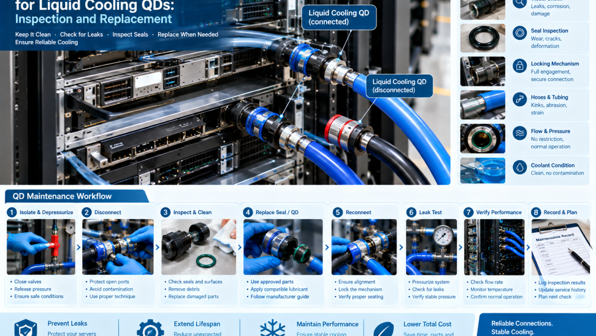
A Practical QD Maintenance Workflow
A structured maintenance procedure can follow this sequence:
Step 1: Review System Status
Confirm operating condition, coolant type, pressure, temperature, and maintenance history.
Step 2: Isolate the Circuit
Follow the system’s isolation procedure.
Step 3: Depressurize Safely
Confirm that the relevant section is at the required service condition.
Step 4: Inspect the QD
Check body, locking mechanism, seals, and surrounding hose.
Step 5: Disconnect Carefully
Protect open ports from contamination.
Step 6: Replace or Service
Install the approved replacement component or seal.
Step 7: Reconnect
Verify alignment and full locking.
Step 8: Leak Test
Use the approved test procedure.
Step 9: Verify Flow and Temperature
Confirm that the cooling system performs normally.
Step 10: Update Maintenance Records
Document the work, component, and test results.
What Makes a Good QD Maintenance Program?
A robust program combines:
Inspection
Cleanliness
Correct installation
Coolant compatibility
Leak testing
Flow verification
Thermal verification
Lifecycle records
Manufacturer guidance
No single maintenance action is sufficient on its own.
Quick disconnects are small components, but they can play an important role in the reliability and maintainability of liquid-cooling systems.
As AI infrastructure adopts higher-density computing and more sophisticated liquid-cooling architectures, reliable QDs become increasingly important.
Effective maintenance should focus on more than simply replacing a connector after failure.
It should include:
Routine inspection → cleanliness control → seal assessment → connection verification → leak testing → flow monitoring → thermal verification → lifecycle documentation
Replacement timing should be based on manufacturer guidance, operating conditions, connection cycles, inspection results, and system criticality rather than relying on a universal schedule.
For AI and high-performance computing environments, the best QD maintenance strategy is ultimately one that minimizes unexpected leakage, preserves cooling performance, and makes servicing predictable.
The goal is not simply to keep a quick disconnect connected.
It is to ensure that every connection in the liquid-cooling system continues to support:
Stable flow + reliable sealing + efficient heat transfer + safe maintenance + long-term system uptime.
That is the foundation of reliable liquid-cooling infrastructure.