A Practical, Replicable Guide for EPC Teams and Field Technicians
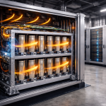
PV + storage inverters—whether hybrid, AC-coupled, or DC-coupled—are the operational “brain” of small industrial and commercial energy systems. When they fail or operate abnormally, the entire PV + BESS system can stall, leaving customers without peak shaving, backup capacity, or energy optimization.
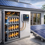
Field data from small commercial and industrial installations (10–100 kW PV with 10–200 kWh storage) shows that over 70% of inverter-related issues are predictable, and most can be resolved quickly with a structured troubleshooting framework.
This article provides a replicable, technician-friendly troubleshooting framework, validated through real field deployments and suitable for EPCs, installers, and O&M teams looking to standardize their workflow.
1. Understanding the Inverter’s Role in PV + Storage Systems
A PV + storage inverter typically manages:
- PV input and MPPT control
- Battery charge/discharge logic
- Grid synchronization
- Backup switching
- EMS/BMS communication
- Load balancing and export limits
Failures often originate from one of five key subsystems:
- DC-side (PV, battery)
- AC-side (grid, load)
- Communication (EMS/BMS/meters)
- Thermal management
- Configuration & commissioning parameters
A structured framework must cover all five.
2. A Standardized Troubleshooting Framework
Step 1 — Identify the Fault Category (Fast Diagnosis)
Most inverter faults fall into these categories:
| Fault Type | Symptoms | Common Root Cause |
|---|---|---|
| DC Fault | No PV charge, low voltage, battery not recognized | Wiring, wrong polarity, loose terminals |
| AC Fault | Grid sync error, CT mismatch, phase reversal | Wrong wiring, unstable grid |
| Communication Fault | Battery SOC not showing, EMS offline | RS485/CAN wiring, protocol mismatch |
| Thermal Fault | Derating, shutdown, hotspot alarms | Heat buildup, poor airflow |
| Parameter/Config Error | Wrong SOC, no backup, unstable | Incorrect commissioning |
A technician must categorize the fault first, then drill down.
3. DC-Side Troubleshooting (PV and Battery)
3.1 PV Input Issues
Common Symptoms
- MPPT voltage too low
- PV power fluctuates abnormally
- PV detected but not charging
Checklist
- Check polarity on each MPPT string
- Verify string voltage = consistent across similar strings
- Ensure all MC4 connectors are fully locked
- Inspect shading or soiling
- Confirm proper grounding
Technical Tip
If two MPPTs show >20% power difference under similar irradiation, the issue is almost always string wiring or connection quality.
3.2 Battery Input Issues
Common Symptoms
- Inverter does not detect battery
- Overcurrent/overvoltage alarms
- Battery charging disabled
Checklist
- Verify BMS-Inverter communication cable (CAN/RS485)
- Check battery voltage within allowed range
- Confirm correct battery type in inverter settings
- Ensure battery breaker is fully engaged
- Measure DC bus voltage for abnormal fluctuations
Field Example
A 48 V low-voltage system repeatedly disconnected due to voltage sag during motor startup.
Solution: limit inverter discharge current and reallocate motor load to a non-backed-up circuit.
4. AC-Side Troubleshooting (Grid, Load, Phase Issues)
4.1 Grid Synchronization Failures
Symptoms
- “Grid over/under voltage”
- “Frequency out of range”
- “Phase mismatch”
Checklist
- Verify L–N and L–L voltages
- Check phase sequence (L1-L2-L3 order)
- Inspect grounding and neutral integrity
- Confirm grid parameters match inverter specs
- Reduce wire length or size to limit voltage drop
Common Cause
Wrong CT orientation or reversed phase sequence is responsible for nearly 40% of AC-side faults.
4.2 Load-Side Issues
Symptoms
- Inverter overload alarms
- Sudden shutdown when large loads start
- Unstable voltage on backup circuits
Checklist
- Identify surge loads > inverter’s peak rating
- Reallocate inductive/motor loads to non-critical circuits
- Ensure neutral is properly shared between backup and non-backup circuits
- Measure actual load profile over 24 hours
Engineering Insight
Small PV + storage inverters often use software-based current limiting, so distributing load correctly is critical for reliability.
5. Communication Troubleshooting (EMS/BMS/CT/Smart Meter)
5.1 Communication Failure Symptoms
- SOC not updating
- Battery “offline”
- Energy meter not recognized
- EMS cannot read PV or battery data
Checklist
- Verify CAN/RS485 pinout according to manufacturer spec
- Ensure shielded twisted-pair cable for long runs
- Terminate RS485 bus with 120Ω resistors
- Inspect for protocol version mismatch
- Check EMS address settings
Common Misconfiguration
Mixed baud rates or mixed protocol versions (Modbus RTU vs CAN-based BMS) cause intermittent failures that appear as hardware issues but are purely software/communication problems.
6. Thermal Troubleshooting
Symptoms
- Derating during midday
- High temperature alarms
- Reduced charging/discharging power
Checklist
- Verify clearance around inverter
- Inspect dust buildup on heat sinks
- Ensure fans are operational
- Check enclosure ventilation
- Perform thermal imaging
Case Insight
A 20 kVA hybrid inverter installed in a small metal cabinet derated daily.
After adding a duct and 40 W fan, the derating completely disappeared.
7. Configuration and Commissioning Errors
This is the most common issue, especially for small commercial PV + storage deployments.
Typical Symptoms
- Backup not working
- Wrong SOC behavior
- Frequent grid switching
- PV not charging the battery
- Export limit not functioning
Checklist
- Verify CT installation direction and phase binding
- Ensure correct battery protocol selection
- Set SOC windows appropriately
- Configure export limit (zero-export or adjustable mode)
- Apply correct power modes (self-consumption / peak shaving / backup-first)
- Update firmware consistently across modules
Pro Tip
Creating standard commissioning templates reduces configuration errors by more than 60%.
8. A Replicable Troubleshooting Workflow for EPCs
Below is a practical flow your technicians can use onsite:
- Identify fault type (AC, DC, communication, thermal, config)
- Check wiring first—most issues are physical, not software
- Verify communication bus integrity
- Check configuration parameters against your EPC standard template
- Test inverter under controlled load
- Review historical logs to identify recurring patterns
- Document findings for reproducible training
This flow dramatically simplifies troubleshooting for large project portfolios.
9. Mini Case Study: Troubleshooting a PV + Storage System at a Logistics Warehouse
Site Profile
- 25 kW PV
- 40 kWh lithium battery
- 15 kVA hybrid inverter
- Warehouse with forklifts and lighting loads
Symptoms
- Inverter randomly disconnected from grid
- PV charging stopped intermittently
- SOC stayed fixed at 65%
Diagnosis
- CT polarity reversed → incorrect load reading
- CAN cable damaged during installation → intermittent battery communication
- Cabinet temperature reaching 48°C → thermal derating
Fixes
- Corrected CT phase and polarity
- Replaced CAN cable and added strain relief
- Installed ventilation fan and added air gap
Result
- Grid disconnection resolved
- PV charging stable
- SOC accuracy restored
- Operating efficiency improved by ~18%
- 70% of inverter issues come from wiring, communication, or configuration errors—not hardware failures.
- Using standardized templates for installation and commissioning reduces field failures significantly.
- Proper CT orientation, grounding, and phase sequence are essential for accurate inverter operation.
- Thermal design is often underestimated in small commercial deployments.
- A clear troubleshooting workflow enables faster resolution and fewer repeat visits.