

Design Principles, Integration Guidelines, and Field-Proven Lessons for Reliable Operation
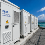
For small energy storage systems (ESS) in the 10–200 kWh class—widely used in workshops, telecom sites, warehouses, microgrids, and industrial utilities—communication architecture is one of the most overlooked yet decisive factors for system reliability.
Even when power electronics, batteries, and EMS software are correctly selected, poor communication design can cause:
- Unstable SOC reporting
- Random inverter shutdowns
- Incorrect CT readings
- Battery “offline” status
- Backup failure during grid outages
- Performance loss due to wrong control logic
- Troubleshooting costs and repeat site visits
This article presents a replicable, field-tested communication architecture framework tailored for EPC teams, technicians, and system integrators building small ESS.
1. Why Communication Architecture Matters in Small ESS
In small industrial sites, unlike utility-scale plants, communication lines are exposed to:
- Noise from motors, compressors, welding machines
- Irregular installation spaces
- Variable grounding conditions
- Long cable distances and improper shielding
- Mixed-brand equipment integration
Because of these realities, 80% of ESS reliability issues originate from communication, not hardware.
Thus, designing a robust communication structure is essential for stable operation and future scalability.
2. Core Components of Small ESS Communication Architecture
A typical small ESS includes communication channels between:
- Inverter ↔ Battery BMS
- Inverter ↔ EMS / Monitoring Platform
- Inverter ↔ Smart Meter / CT
- ESS ↔ Site SCADA or Local Controller
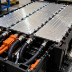
- Battery Pack ↔ BMS Modules (internal)
Each interface uses different protocols and physical media, such as:
- CAN bus (battery protocol, fast & reliable)
- RS485 (Modbus RTU) (meters, EMS external devices)
- Ethernet (TCP/IP) (networked EMS, cloud monitoring)
- WiFi/4G (remote communication, optional)
A well-designed architecture must integrate all cleanly without interference.
3. Best Practices for ESS Communication Design
3.1. Prioritize Hardwired Connections Over Wireless
Wireless links are suitable for monitoring, not for core control.
Rules:
- Use wired CAN for battery–inverter communication
- Use wired RS485 for CT/meter communication
- Use Ethernet for EMS or SCADA
- Avoid WiFi for any control function
- Only use 4G for remote monitoring fallback
Reason:
Wireless latency and dropouts cause SOC misalignment and unexpected inverter behavior.
3.2. Use Shielded Twisted-Pair Cables for CAN and RS485
Industrial environments generate strong EMI; proper cable selection is critical.
Recommended Cable Specs:
| Protocol | Cable Type | Shielding | Notes |
|---|---|---|---|
| CAN | Shielded Twisted Pair (STP) | Foil + braid | Max 40 m recommended |
| RS485 | Shielded Twisted Pair (STP) | Foil | Terminate with 120Ω |
| Ethernet | CAT6 STP | Shielded | Avoid running parallel to AC cables |
Avoid UTP cables for ESS-critical communication.
3.3. Maintain Proper Grounding and Avoid Ground Loops
Many small ESS faults originate from poor grounding.
Best Practices:
- Connect shields at one end only to avoid ground loops
- Ensure inverter, battery rack, and cabinet share a common earth point
- Avoid mixing IT grounding (telecom cabinets) with TN grounding (industrial floor)
Result:
Cleaner signals, fewer CAN dropouts, reduced interference.
3.4. Set Correct Communication Termination
Incorrect termination causes:
- Intermittent BMS offline
- No SOC updates
- Battery not recognized
Rules:
- CAN: Both ends of the bus require termination (often built-in on devices)
- RS485: Terminate with 120Ω resistor at the last device
- Daisy-chain only; never star-topology communication
This ensures signal integrity on long runs.
3.5. Map Communication Parameters Consistently
This includes:
- Baud rate
- Device IDs
- Slave addresses
- Protocol type (Modbus RTU, CANOpen, proprietary CAN)
- Register mappings
Zero mismatch tolerance should be enforced.
A single wrong baud rate or ID can take down an entire ESS.
3.6. Separate Communication and Power Cabling
To avoid EMI and coupling issues:
- Keep signal cables 20–30 cm away from AC cables
- Cross at 90° when unavoidable
- Use cable conduits or trays to separate
- Avoid coiling excess communication cable
These simple rules prevent inverter-BMS communication failure.
4. A Replicable Communication Architecture for Small ESS
This structure can be applied across all EPC projects for standardization.
4.1. Topology Overview
Battery BMS ⇄ CAN ⇄ Inverter ⇄ RS485/Ethernet ⇄ EMS ⇄ Cloud

                         ⇅ RS485
                      Smart Meter/CT
4.2. Key Design Rules
- Battery → Inverter:
Dedicated CAN line, short as possible, shielded. - Meter/CT → Inverter:
RS485 Modbus RTU, daisy-chained. - Inverter → EMS:
Ethernet preferred; RS485 for isolated sites. - EMS → Cloud:
Ethernet primary, 4G as secondary. - SCADA Integration:
Modbus TCP/IP via gateway.
This architecture supports both present operation and future scaling.
5. Commissioning Checklist for ESS Communication
A technician-friendly checklist:
Step 1 — Physical Inspection
- Shielded cables used?
- Shield grounded at one end only?
- Cable separation maintained?
- No damaged connectors?
Step 2 — Electrical Verification
- 120Ω termination resistor?
- Correct bus polarity?
- Grounding continuity?
Step 3 — Protocol Settings
- Baud rate correct?
- Device IDs unique?
- Same Modbus register map?
- Correct battery protocol selected?
Step 4 — Functional Tests
- Battery SOC synchronization
- PV charging data accuracy
- CT/meter active power verification
- EMS command response (charge/discharge/stop)
Step 5 — Logging & Documentation
- Cable routing photos
- Parameter backup
- Device firmware versions
- Network topology diagram
This checklist helps reduce O&M issues by more than 50%.
6. Small ESS Communication Failure Modes and Solutions
| Failure Mode | Symptoms | Solution |
|---|---|---|
| CAN noise | BMS offline, SOC frozen | Replace with shielded cable; re-route |
| RS485 miswiring | CT reads negative | Reverse polarity; correct terminals |
| Protocol mismatch | Battery not recognized | Select correct CAN protocol |
| Ground loops | Random alarms | Connect shield one-side only |
| Long cable runs | Unstable SOC | Add repeater or shorten cable |
| Overloaded network | EMS lag | Switch to wired Ethernet |
Most failures are preventable through good design.
7. Case Study: Upgrading Communication at a Textile Workshop ESS
Site Profile
- 20 kW PV
- 30 kWh storage
- 10 kVA hybrid inverter
- Multiple motor loads (high EMI environment)
Issues
- SOC stuck at 50%
- PV power readings unstable
- Random inverter shutdowns
- Battery “offline” twice per day
Diagnosis
- CAN cable was unshielded
- Shield grounded on both ends → ground loop
- RS485 meter cable routed next to 3-phase AC wiring
- Wrong Modbus address on meter
Fixes
- Replaced CAN with STP cable
- Grounded shield on one end only
- Re-routed RS485 away from AC power
- Corrected Modbus address
Results
- SOC updates stable
- No more inverter shutdowns
- PV readings accurate
- System availability improved significantly
This demonstrates that communication quality equals system reliability in small ESS.
8. Key Takeaways for EPC and O&M Teams
- Communication architecture is critical—often more than hardware specs.
- CAN for batteries, RS485 for meters, Ethernet for EMS is the ideal structure.
- Shielded twisted pair cabling is mandatory in industrial environments.
- Proper grounding and termination prevent most communication faults.
- Standardization across projects reduces cost, risk, and troubleshooting time.
- A replicable architecture ensures long-term system reliability.