
Practical Fault Isolation, Diagnostic Routines, and Field-Proven Recovery Methods
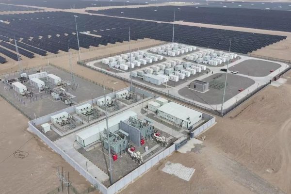
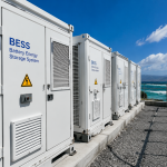
Modular energy storage systems (ESS) are designed to simplify installation and improve scalability—but troubleshooting in the field still requires a precise, step-by-step methodology.
From small commercial systems to mid-size industrial deployments, most faults originate from predictable causes: communication mismatches, protection misconfigurations, cabling issues, thermal imbalance, and commissioning oversights.
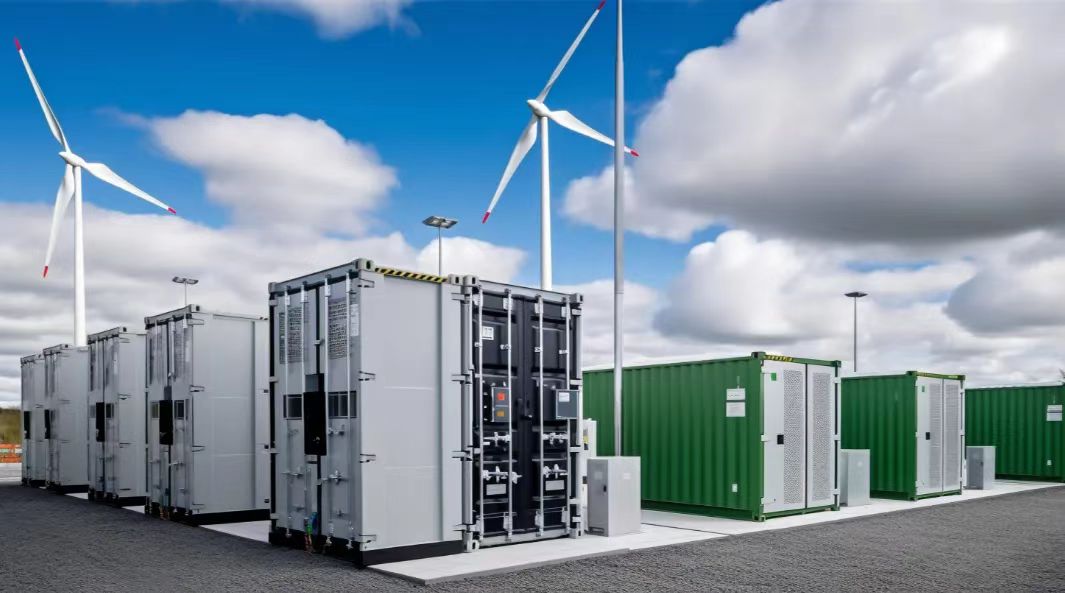
This guide provides a practical, technician-ready troubleshooting framework tailored for modular ESS deployed in commercial/industrial scenarios.
It focuses on real-world issues found in early deployments and offers replicable diagnostic procedures that EPCs can standardize across teams.
1. The Five Most Common Categories of ESS Issues
Field experience shows that 90% of ESS problems fall into five groups:
- Communication Issues
(BMS ↔ PCS, PCS ↔ EMS, module ↔ module) - Protection and Interlock Failures
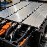
(DC breakers, pre-charge, fuse trips) - Battery Module Issues
(Cell imbalance, over-temp, incorrect SOC) - Inverter/PCS Operation Faults
(Grid limits, overload, configuration mismatch) - Thermal System Malfunction
(Hot spots, air path blockage, fan failures)
Each category is addressed below with step-by-step troubleshooting routines.
2. Step-by-Step Troubleshooting Framework
This is a field-ready method technicians can follow onsite:
Step 1 — Identify the Fault Origin (Battery / PCS / EMS)
Use the system alarms and LEDs to determine which subsystem raised the initial flag.
Typical indicators:
- BMS alarm → battery module
- PCS alarm → inverter/AC/DC conversion
- EMS alarm → load/grid logic or communication
Technicians should avoid clearing alarms immediately.
First determine where the fault originated and whether it cascaded.
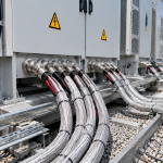
Step 2 — Verify Physical & Electrical Conditions
Before checking software parameters, confirm physical installation issues:
Checkpoints
- DC breaker positions
- AC incoming breaker
- Cable torque verified
- Grounding continuity
- Module connectors fully seated
- Signs of overheating, discoloration, loose lugs
Over 30% of early field faults come from physical conditions—not firmware.
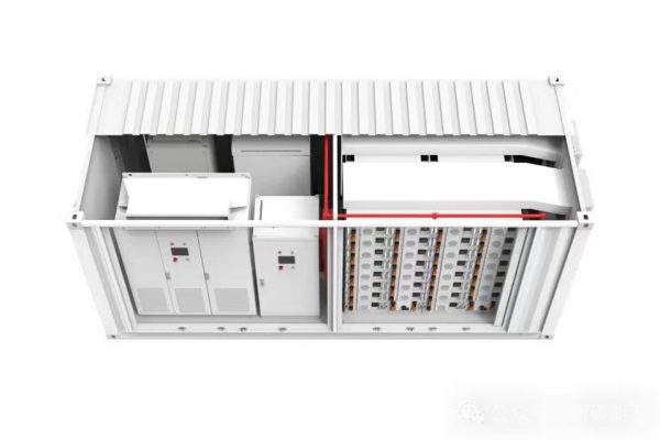
Step 3 — Isolate Affected Module/Subsystem
For modular ESS, isolating the problem component is easy:
- Shut down affected battery rack
- Disconnect communication cable
- Disable specific PCS channel
- Operate ESS in reduced capacity
Modular architecture allows technicians to restore partial operation while repairing one block.
Step 4 — Follow Category-Specific Troubleshooting Procedures
Below are field-proven steps per fault type.
3. Troubleshooting Guide by Fault Category
Category A: Communication Faults (Most Common)
Typical errors:
- BMS comm timeout
- PCS–Battery protocol mismatch
- EMS not receiving SOC data
- RS485/CAN wiring reversed
Field Diagnostic Steps
- Check communication cables (RJ45/CAN/RS485).
- Confirm correct port on BMS and PCS.
- Verify protocol version setting.
- Confirm CAN baud rate / RS485 address.
- Restart PCS → then BMS (order matters).
- Reload communication template in EMS.
Fast Recovery Tip
If one module fails:
- Remove module from communication chain
- Reroute BUS to bypass
- Replace/repair module while system runs at reduced capacity
Category B: DC Protection & Interlock Failures
Symptoms:
- PCS cannot start
- DC bus undervoltage
- Pre-charge failure
- External DC breaker trip
Checklist
- DC breaker ON? Torque secure?
- Pre-charge resistor intact?
- Battery voltage within PCS start-up window?
- Fuse continuity check
- Emergency stop circuit closed
Field Fix
- Reset DC breaker
- Retry PCS startup sequence
- Replace fuse if blown
- Perform pre-charge manually (if allowed by SOP)
Category C: Battery Module Faults
Typical BMS alerts:
- Cell over-voltage
- Cell under-voltage
- Cell imbalance
- Over-temperature
- Module offline
Troubleshooting Procedure
- Identify module with highest deviation.
- Check module connector seating.
- Measure module voltage manually.
- Verify temperature sensor readings.
- Run BMS balancing cycle.
- Restore module; if unsuccessful, isolate and replace.
Permanent Fix
Establish routine balancing via EMS to prevent drift.
Category D: PCS / Inverter Issues
Common problems:
- AC overcurrent
- Grid over/under-frequency
- Inverter overload
- Incorrect CT polarity
- Phase rotation mismatch
Diagnostic Flow
- Confirm AC source parameters with meter.
- Check inverter firmware/parameter set.
- Validate CT installation (direction matters).
- Reduce load, restart PCS.
- Re-run commissioning configuration.
Typical Field Fixes
- Correct phase order
- Adjust ramp rate
- Reduce command power based on grid limits
Category E: Thermal System Malfunctions
Indicators:
- Uneven module temperatures
- PCS derating
- Hotspot alarms
- Fan overcurrent
Troubleshooting Steps
- Verify fan power supply.
- Check intake/exhaust airflow direction.
- Inspect air filters for blockage.
- Measure temperature at each module.
- Check whether cabinet doors create airflow obstruction.
Fast Fix
- Add temporary external fan
- Clean filters
- Remove obstacles
- Separate inverter from battery compartment
Long-term: standardize airflow design per module.
4. Troubleshooting Flowchart (Technician Playbook)
1. Alarm occurs → Identify subsystem
⬇
2. Physical inspection (cables, torque, breaker, airflow)
⬇
3. Isolate module/rack
⬇
4. Apply category troubleshooting routine (A–E)
⬇
5. Restore partial system operation (if possible)
⬇
6. Perform full recovery or module replacement
⬇
7. Update monitoring logs + customer report
This flowchart ensures every technician follows the same logic.
5. Field-Proven Preventive Maintenance Tasks
To minimize troubleshooting frequency:
Monthly
- Check SOC accuracy
- Inspect battery temperature history
- Review BMS alarm log
Quarterly
- Cable torque verification
- Filter cleaning
- Firmware update
- EMS parameter audit
Annually
- Thermal imaging of cabinets
- Full communication verification
- Cell balance deep cycle (if needed)
Preventive maintenance reduces onsite failures by 40–60%.
6. Real-World Case Example
System: 50 kW PCS + 120 kWh modular LFP battery
Issue: PCS shutdown during peak load
Symptoms:
- BMS stable
- No DC alarm
- Temperature normal
- PCS “Grid Overcurrent”
Troubleshooting Steps Per Toolkit
- Checked AC breaker → normal
- Verified phase sequence → incorrect after facility rewiring
- Corrected phase rotation
- Re-ran PCS self-test
- Issue resolved
Outcome:
System returned to normal operation in 35 minutes with no component replacement.
A modular ESS simplifies hardware complexity—but troubleshooting still requires a structured and repeatable method.
Field technicians using a unified troubleshooting toolkit can:
- Isolate failures faster
- Restore partial operation immediately
- Prevent misdiagnosis
- Minimize customer downtime
- Maintain consistent system reliability across sites
A well-designed troubleshooting framework is essential for scaling ESS deployment across commercial and industrial environments.