
When building a PV+storage system, it’s tempting to focus only on big specs — like inverter power or battery capacity. But one of the most common reasons for system underperformance lies deeper: mismatch between solar panels, inverters, and batteries.
Even with high-quality components, poor matching can cause inefficiency, voltage drop, inverter shutdowns, or even battery damage.
This article breaks down the main challenges in system matching and how to avoid costly mistakes in residential and C&I projects.
1. Why Matching Matters
A solar + storage system is an electrical ecosystem — every part must “speak the same language.”
If one component is out of sync, performance suffers across the whole system.
| Component | Function | Common Matching Issue |
|---|---|---|
| PV panels | Generate DC power | Voltage/current not matching inverter input |
| Inverter | Convert DC–AC and manage charge/discharge | Power rating mismatch |
| Battery | Store DC energy | Voltage/communication mismatch |
⚡ The inverter is the “bridge” — it must communicate and balance both sides correctly.
2. Voltage Mismatch: The Silent Efficiency Killer
The PV array voltage must fall within the inverter’s MPPT (Maximum Power Point Tracking) window, and the battery voltage must align with the inverter’s DC bus.
🔹 Common Problems
- PV voltage too low: inverter never reaches its MPPT, resulting in poor energy harvest.
- PV voltage too high: inverter overvoltage fault → automatic shutdown.
- Battery voltage range incompatible: inverter cannot charge/discharge correctly.
✅ Example
If an inverter’s PV input range is 250–500V, and you connect 6 panels (41V each):
- 6 × 41V = 246V → below the minimum limit!
You’ll lose generation during most daylight hours.
🧠 Tip: Always check inverter datasheets for “MPPT voltage range” and “max PV open-circuit voltage (Voc)” before finalizing string design.
3. Current (Ampere) Limitations
Inverters have a maximum PV current per MPPT and a maximum charge/discharge current for batteries.
🔹 Typical Issues
- PV string output > inverter current limit → power clipping.
- Battery current exceeds inverter charging capacity → slower charging or fault.
✅ Example
If your inverter supports max 13A PV input per MPPT, but panels can produce 15A, the inverter clips at 13A — you lose up to 15% yield during peak sunlight.
⚙️ Always design with inverter current limits in mind — not just power rating.
4. Communication and Protocol Compatibility
Modern hybrid inverters and batteries require data communication to synchronize SOC (state of charge), voltage, and safety commands.
🔹 Common Compatibility Barriers
- Different CAN / RS485 protocols
- Missing certified compatibility list
- Inverter firmware not supporting the battery brand
✅ Solution
Before ordering, confirm that your battery is listed as compatible on the inverter manufacturer’s website.
If not, check for:
- “Self-defined protocol” or “custom CAN mode” support
- Manual setting of voltage and current limits
📡 A technically “working” system without data sync may charge/discharge unsafely or stop unexpectedly.
5. Power Rating Balance
Your inverter power (kW) should roughly match your PV array (kWp) and battery energy (kWh) to ensure efficient operation.
| Ratio Type | Typical Range | Notes |
|---|---|---|
| PV / Inverter | 1.1–1.3× | Slight oversizing improves yield |
| Battery / Inverter | 1.5–2× (for daily cycling) | Larger batteries need longer charge windows |
⚠️ Common Mistake
Oversizing the PV array and the battery beyond inverter limits — leads to throttled charging and frequent inverter faults.
🧩 Think of the inverter as a traffic controller — it can only manage what it’s rated for.
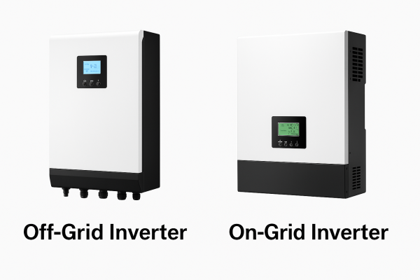
6. AC-Coupled vs. DC-Coupled Systems
Different architectures require different matching strategies.
DC-Coupled (Hybrid Inverter)
- PV → DC → Battery → Inverter → AC
- Single inverter manages both PV and storage
- Easier to control efficiency and charging
AC-Coupled (Separate Inverter)
- PV inverter → AC → Battery inverter
- Two systems communicate via grid frequency or external controller
🔹 Matching Challenges
- DC-coupled: ensure voltage & protocol alignment
- AC-coupled: ensure grid sync and control logic compatibility
⚡ DC coupling is simpler for new systems; AC coupling fits retrofit projects.
7. Temperature and Environmental Effects
Voltage, current, and battery performance all shift with temperature.
🔹 PV Panels
- Cold weather increases voltage → risk of inverter overvoltage.
- Hot weather reduces voltage → risk of inverter shutdown.
🔹 Batteries
- Capacity drops at low temperatures.
- High heat accelerates degradation or triggers BMS limits.
🌡️ Always simulate system performance across temperature extremes before shipment.
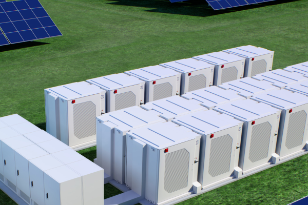
8. Storage Voltage Scaling with System Size
- Small residential: 48V or 100V
- Mid-scale commercial: 200–400V
- Large C&I / Utility: 600–1000V
If you mismatch a 48V battery with a 400V inverter, it simply won’t operate.
Hybrid inverters often specify a narrow working voltage range — e.g., 120–550VDC.
🧠 Design Rule:
Battery nominal voltage ≈ 70–80% of inverter’s rated DC voltage.
9. Mixed Brands and OEM Components
Many distributors buy panels, inverters, and batteries from different suppliers — this creates hidden integration risks.
🔹 Common Pitfalls
- Firmware mismatch → no charge control
- Slightly different CAN definitions → battery error
- Certification conflicts → customs or warranty issues
✅ How to Mitigate
- Use components from brands with verified compatibility lists.
- Request factory pre-commissioning reports from your supplier.
- Conduct bench testing before shipment for large systems (>100 kWh).
10. Installer’s Checklist: Before Shipment
| Checkpoint | What to Confirm |
|---|---|
| PV String Voltage | Within MPPT range |
| PV Current | Below per-MPPT limit |
| Battery Voltage | Matches inverter DC range |
| Communication | CAN/RS485 protocol tested |
| Firmware | Latest version with compatible library |
| Certifications | UL/IEC compliance for all components |
| Grounding | Consistent polarity and protection scheme |
✅ Performing these checks before shipment can save weeks of troubleshooting on site.
11. Real-World Case: 100 kW C&I Hybrid System
- PV array: 130 kWp (540W panels)
- Inverter: 100 kW hybrid (max PV 135 kWp, 600V MPPT)
- Battery: 200 kWh, 384V nominal
During installation, the team noticed charging limited to 20 kW.
Root cause: battery firmware not matching inverter protocol — BMS restricted current.
After updating firmware and recalibrating parameters, full 100 kW charge rate was restored.
⚙️ Always test system behavior under real load before handover.
12. How Suppliers Can Help
Good suppliers offer more than just components — they provide integration support:
- Pre-defined compatible configurations
- Wiring diagrams and setting templates
- Remote commissioning assistance
🧭 A supplier with strong technical backup saves you hours of trial and error.
Matching PV panels, inverters, and batteries isn’t just about wattage — it’s about electrical harmony.
A mismatch in voltage, current, or communication can ruin system efficiency or safety.
✅ Key takeaways:
- Always match PV voltage/current to inverter specs.
- Ensure protocol-level compatibility between inverter and battery.
- Verify system ratios (PV/inverter/battery) are balanced.
- Test configurations before shipment — not after installation.
When properly matched, your system delivers:
- Higher efficiency
- Longer battery life
- Fewer site issues
- Happier clients
⚡ In solar and storage, integration is everything — precision at design stage saves cost at deployment.