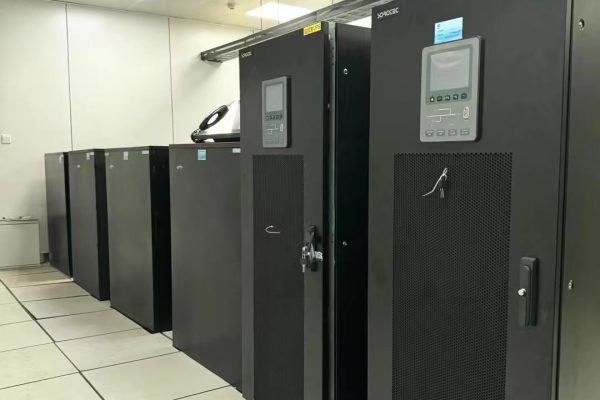


In modern energy storage and solar PV systems, reliable communication between components is as critical as the hardware itself.
Inverters, batteries, and energy management systems (EMS) must exchange data seamlessly to ensure safe operation, efficiency, and real-time monitoring.
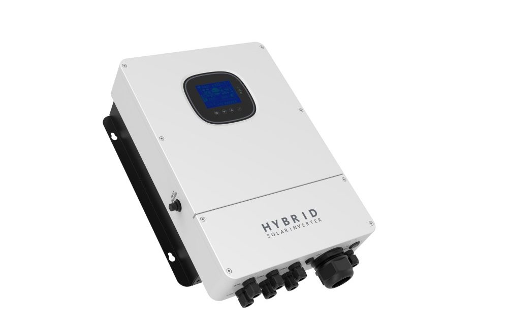
Whether you’re configuring a hybrid inverter, battery management system (BMS), or a commercial ESS (Energy Storage System), understanding the major communication protocols — MODBUS, RS485, and CAN — is essential for system integration and troubleshooting.
This article explains the purpose, differences, and use cases of these three key communication protocols — and how to select the right one for your next PV + storage project.
1. Why Communication Matters in ESS and Inverter Systems
In a PV + Battery + Inverter setup, several intelligent devices must constantly communicate:
- Inverter ↔ BMS: for battery voltage, current, SOC, temperature, protection status
- Inverter ↔ PV Controller / MPPT: for DC input data and control
- Inverter ↔ EMS / SCADA: for system-level monitoring and dispatch
- Inverter ↔ Meter / Smart Grid: for export/import power control
Without standardized communication protocols, each brand or component would require a custom interface, making integration slow and unreliable.
💡 Communication = Control + Safety + Optimization
Without proper data exchange, the system can’t balance charging, discharging, or protection correctly.
2. Overview of the Main Protocols
| Protocol | Layer | Common Use | Typical Devices |
|---|---|---|---|
| RS485 | Physical Layer (Hardware Interface) | Serial communication backbone | Inverters, BMS, meters |
| MODBUS | Application Protocol (Built on RS485) | Data exchange standard | EMS, SCADA systems |
| CAN (Controller Area Network) | Physical + Data Link Layer | High-speed communication between controllers | BMS, EV batteries, hybrid inverters |
⚙️ In simple terms:
RS485 defines how signals are transmitted,
MODBUS defines what data is sent,
CAN defines how multiple controllers communicate efficiently.
3. RS485: The Backbone of Industrial Communication
What It Is
RS485 is a serial communication standard that uses differential signaling to transmit data between multiple devices on the same line.
It’s been the foundation of industrial systems for decades.
Key Features
- Half-duplex communication (one direction at a time)
- Supports up to 32 nodes per bus
- Cable length: up to 1200 meters
- Data rate: typically 9600–115200 bps
- Noise-resistant and ideal for long-distance applications
Advantages
✅ Very stable for long cable runs
✅ Low cost and simple wiring (A/B differential pair)
✅ Widely supported by industrial equipment
Limitations
⚠️ Slower compared to CAN
⚠️ Requires polling (master-slave model) — devices can’t speak simultaneously
⚠️ Data packet structure is not defined (needs a protocol like MODBUS)
📡 Common Use:
RS485 is the physical layer for most MODBUS-RTU communication in inverters, BMS, and meters.
4. MODBUS: The Universal Language for Industrial Data
What It Is
MODBUS is an open communication protocol that defines how data is structured and transmitted between master and slave devices.
It is built on top of RS485, TCP/IP, or Ethernet layers.
Two Main Types
- MODBUS RTU — Serial communication over RS485
- MODBUS TCP — Ethernet-based (for large C&I systems or SCADA)
How It Works
- The master (e.g., inverter or EMS) sends requests.
- The slave (e.g., BMS or meter) replies with data values.
- Data is organized in registers (e.g., voltage, current, SOC, alarms).
Example MODBUS Registers:
| Address | Function | Description |
|---|---|---|
| 30001 | Input Register | Battery voltage |
| 30002 | Input Register | Battery current |
| 40001 | Holding Register | Set charge current |
| 40002 | Holding Register | Set discharge limit |
Advantages
✅ Open standard, widely supported
✅ Flexible — can run on RS485 or Ethernet
✅ Easy to integrate with SCADA, EMS, or data loggers
Limitations
⚠️ Master-slave only (no peer-to-peer)
⚠️ Limited speed (~100 kbps typical)
⚠️ Each manufacturer may use different register maps, requiring matching documentation
💬 Common Use:
- Communication between inverter and EMS
- Data acquisition from meters or sensors
- Remote monitoring systems
5. CAN: Fast, Reliable Communication for Batteries and Inverters
What It Is
CAN (Controller Area Network) was originally developed for automotive systems, enabling multiple controllers (ECUs) to communicate without a master device.
It is now widely used in battery management systems (BMS) and energy storage inverters.
Key Features
- Multi-master communication (any device can send messages)
- High speed: up to 1 Mbps
- Short cable length (up to 40 m typical for high speed)
- Built-in error detection and correction
- Message-based (not address-based)
Advantages
✅ Fast and reliable — ideal for real-time control
✅ Peer-to-peer communication (no single point of failure)
✅ Low error rate, automatic retransmission
✅ Compact data frames (up to 8 bytes per message)
Limitations
⚠️ Shorter distance than RS485
⚠️ Requires compatible CAN message IDs between devices
⚠️ Not human-readable (binary structured data)
🔋 Common Use:
- Communication between battery BMS and inverter
- High-speed protection commands (e.g., overcurrent shutdown)
- Automotive and EV-grade battery packs
6. Protocol Comparison Table
| Feature | RS485 | MODBUS | CAN |
|---|---|---|---|
| Type | Hardware Interface | Communication Protocol | Hardware + Protocol |
| Communication | Serial (half-duplex) | Master–Slave | Multi-Master |
| Speed | 9.6–115 kbps | 9.6–115 kbps | Up to 1 Mbps |
| Cable Length | Up to 1200 m | Up to 1200 m | Up to 40 m |
| Topology | Bus | Bus | Star/Bus |
| Use Case | General data transfer | Industrial automation | Real-time battery control |
| Typical Devices | Inverters, meters | EMS, SCADA | BMS, EV, hybrid inverter |
⚙️ In summary:
- RS485 = Physical wire
- MODBUS = Data language
- CAN = Fast control network
7. Integration Examples in Energy Storage Systems
Example 1: Residential PV + Battery
- RS485 used for inverter ↔ meter data
- CAN used for inverter ↔ BMS communication
- MODBUS RTU used for remote data logging
Example 2: Commercial 250 kW / 500 kWh System
- MODBUS TCP for EMS ↔ Inverter communication
- RS485 for inverter ↔ smart meter
- CAN bus between inverters and battery racks
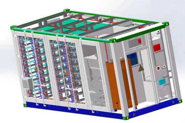
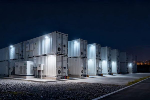
Example 3: Containerized BESS (1 MWh+)
- CAN used internally within battery racks
- MODBUS TCP connects inverter clusters to SCADA
- RS485 provides backup data links
🧠 Design Tip:
Always confirm protocol compatibility in advance — mismatched CAN IDs or MODBUS maps are a top cause of commissioning delays.
8. Choosing the Right Protocol for Your Project
| System Type | Recommended Protocol | Reason |
|---|---|---|
| Small Off-Grid or Hybrid Home System | RS485 + CAN | Simple wiring, direct BMS link |
| Commercial PV+ESS with EMS | MODBUS RTU/TCP + CAN | System-level control and real-time battery protection |
| Containerized BESS or Microgrid | MODBUS TCP + CAN | High data throughput, remote SCADA control |
| EV Charging + Storage System | CAN + Ethernet | Fast response and external data sync |
🔧 Rule of Thumb:
- Use CAN for battery-level control
- Use MODBUS for system-level monitoring and SCADA
- Use RS485 as the physical backbone
9. Best Practices for Communication Reliability
- Use shielded twisted-pair cables (e.g., 22AWG, 120Ω impedance)
- Maintain proper grounding and cable termination
- Keep total RS485 bus length under 1200 m
- Avoid star topologies for RS485
- Label all ports clearly during installation
- Match baud rate and parity settings across devices
- Test with manufacturer’s recommended protocol map
⚡ Communication failures are responsible for over 30% of ESS commissioning issues — attention to wiring and protocol setup pays off.
Choosing the right communication protocol is just as important as selecting batteries or inverters.
✅ Key Takeaways:
- RS485: Reliable physical interface for industrial data
- MODBUS: Universal protocol for monitoring and control
- CAN: High-speed real-time communication for battery safety
- Always verify protocol compatibility between inverter and BMS before shipment
As energy storage systems grow more complex, integrating these communication layers effectively ensures stable operation, accurate data, and safe system behavior — the foundation of every professional PV + ESS installation.