
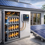
When designing or sourcing small solar + storage systems — typically under 10 kW — installers and buyers often focus on inverters, batteries, and panels.
However, one of the most overlooked (yet essential) areas is the balance of system (BOS) components — especially solar cables and breakers.
The correct selection of cables and protection devices not only improves system efficiency but also prevents overheating, fire risk, and voltage drop.
In small residential or commercial systems, these details can make the difference between a safe, long-lasting system and a costly service call.
This article explains the key technical considerations for solar cables and breakers, helping buyers and installers make confident, code-compliant choices.
1. Why Cable and Breaker Selection Matters
Solar power systems generate high DC currents and operate continuously under outdoor conditions.
Incorrect cable sizing or protection can cause:
- Excessive voltage drop
- Cable overheating and insulation failure
- Arc faults or fire hazards
- Reduced power efficiency
⚙️ Good wiring and protection are the hidden foundation of every reliable solar + storage project.
2. Typical Cable Types in Small PV Systems
| Cable Type | Description | Use Case |
|---|---|---|
| PV Cable (DC cable) | UV-resistant, double-insulated copper cable | Between panels and inverter (string connections) |
| Battery Cable | Flexible, high-current DC cable | Between battery and inverter/DC bus |
| AC Cable | Standard electrical cable (multi-core) | Between inverter and distribution box |
| Communication Cable (RS485/CAN) | Shielded twisted pair | Between inverter, BMS, and monitoring systems |
🔌 Always use cables rated for “solar DC use” — standard electrical cables are not suitable for outdoor PV wiring.
3. Cable Sizing Basics — Voltage Drop and Current Rating
(1) Current Carrying Capacity
Each cable must be rated to carry the maximum system current safely. Icable≥Imax×1.25I_{cable} ≥ I_{max} × 1.25Icable≥Imax×1.25
This 25% safety margin aligns with IEC 60364 and NEC 690.8 standards.
(2) Voltage Drop
To maintain efficiency, total voltage drop should be:
- ≤ 1.5% on DC side (PV to inverter)
- ≤ 2% on AC side (inverter to load)
Use larger cable cross-sections if distance exceeds 20–30 meters.
(3) Cable Cross Section Estimation
| Power (kW) | Voltage (V) | Typical Current (A) | Suggested Cable (mm²) |
|---|---|---|---|
| 3 kW | 48V DC | ~62 A | 16 mm² |
| 5 kW | 48V DC | ~104 A | 25 mm² |
| 10 kW | 230V AC | ~43 A | 6 mm² |
🧮 Always check both continuous current and surge current (from inverter startup).
4. DC Cable Standards and Markings
When purchasing solar cables, look for the following standard markings:
- EN 50618 (Europe) — e.g. H1Z2Z2-K cable
- TÜV 2 PfG 1169 — German standard for PV cable
- UL 4703 — U.S. solar cable standard
- IEC 62930 — International PV cable standard
Key Features to Verify:
- Double-layer insulation (XLPO or cross-linked polymer)
- UV and ozone resistance
- Temperature rating: –40°C to +90°C continuous use
- Rated voltage: 1000 VDC or 1500 VDC
🌞 Certified solar cables ensure durability in outdoor and rooftop environments.
5. Battery Cable Considerations
For DC coupling between inverter and lithium battery:
- Use fine-stranded, flexible copper cable (e.g., welding cable type)
- Ensure both ends have crimped lugs with heat-shrink insulation
- Follow color coding:
- Red: Positive (+)
- Black: Negative (–)
- Green/Yellow: Ground (PE)
Cable Size Example (48V Systems):
| System Power | Max Current | Cable Size (mm²) | Distance |
|---|---|---|---|
| 5 kW | 104 A | 25 mm² | <3 m |
| 8 kW | 166 A | 35 mm² | <3 m |
| 10 kW | 208 A | 50 mm² | <3 m |
⚡ Thick, short battery cables minimize heat buildup and voltage loss during charge/discharge.
6. Breaker Types in Solar Systems
Breakers and fuses protect both equipment and wiring from overcurrent and short circuits.
🔸 1. DC Breakers (for PV input and battery lines)
- Rated for DC voltage (600–1000VDC)
- Must interrupt current in one direction
- Used between PV array → inverter and battery → inverter
🔸 2. AC Breakers (for grid output)
- Rated for AC voltage (230V or 400V)
- Protects inverter output to grid/load
🔸 3. DC Fuses
- Used inside combiner boxes or battery cabinets
- Fast-blow type, rated at 1.5× system current
🔸 4. SPD (Surge Protection Devices)
- Protect against lightning or transient surges
- Installed on both DC (PV side) and AC (grid side)
🧯 Each circuit — PV, battery, and grid — must have its own independent protection.
7. Breaker Selection Criteria
| Parameter | What It Means | Typical Value |
|---|---|---|
| Rated Current (In) | Max current before trip | 16A / 32A / 63A |
| Breaking Capacity (Icu) | Fault current it can safely interrupt | ≥ 6 kA |
| Poles | Number of lines protected | 1P, 2P (DC); 3P, 4P (AC) |
| Voltage Rating | DC or AC rating | 500VDC / 1000VDC / 230VAC |
| Curve Type (AC) | Tripping response | Curve C or D for inverters |
⚙️ Always confirm “DC” labeling — AC-only breakers can’t extinguish DC arcs safely.
8. Practical Example — 5kW PV+Storage System
System Configuration:
- PV Input: 2 strings, 250VDC each, 10A/string
- Battery: 48V, 100Ah × 2 in parallel
- Inverter: 5kW hybrid
Protection Design:
- PV DC cables: 6 mm², H1Z2Z2-K, 1000V rated
- Battery cables: 25 mm² fine-stranded copper
- PV breaker: 2P 1000VDC 16A
- Battery breaker: 2P 125A DC rated
- SPD: DC Type II on PV side, AC Type II on grid side
- AC breaker: 2P 32A Curve C
🔧 Using correctly rated components simplifies installation and ensures compliance with IEC or NEC standards.
9. Common Mistakes in Small System Wiring
| Mistake | Result | Fix |
|---|---|---|
| Using undersized cables | Voltage drop, heating | Use proper current rating + 25% margin |
| Using AC breakers for DC | Arcing and fire risk | Use DC-rated breakers |
| No fuse between battery and inverter | Cable damage during short | Add DC fuse or breaker |
| Long cable runs without compensation | Efficiency loss | Increase cable section or reduce length |
| Poor crimping of lugs | Heat and loose contact | Use hydraulic crimp tool |
| No surge protection | Equipment damage | Install SPD on PV and grid side |
🚫 Overlooking small BOS details is one of the top causes of inverter or battery failure in field installations.
10. Compliance and Certification
For professional installation and export, ensure all components carry valid certifications:
- TÜV / CE / UL marks
- RoHS compliance (for materials)
- IP65 or above for outdoor breakers and junction boxes
📜 Certified components reduce warranty disputes and improve buyer confidence.
11. Maintenance and Inspection Tips
- Tighten all terminals every 6–12 months
- Inspect cable insulation for UV damage or discoloration
- Replace breakers or fuses after any short-circuit event
- Test insulation resistance annually
🧰 Preventive maintenance extends system lifespan and ensures long-term safety.
12.
Even the most advanced inverter or battery system can fail if the cables and breakers are poorly chosen.
For small systems, attention to wiring and protection is just as important as selecting high-efficiency components.
✅ Key Takeaways:
- Use DC-rated solar cables (H1Z2Z2-K / UL4703).
- Keep voltage drop below 1.5% for PV side.
- Size breakers at 125% of nominal current.
- Add fuses, SPDs, and proper grounding.
- Inspect connections regularly for safety.
A well-designed BOS not only ensures compliance but also builds your reputation for professional, durable, and safe solar installations.