

A Practical Guide for Integrators and Project Buyers in Small PV + Storage Systems
Why Compatibility Is a Recurring Headache
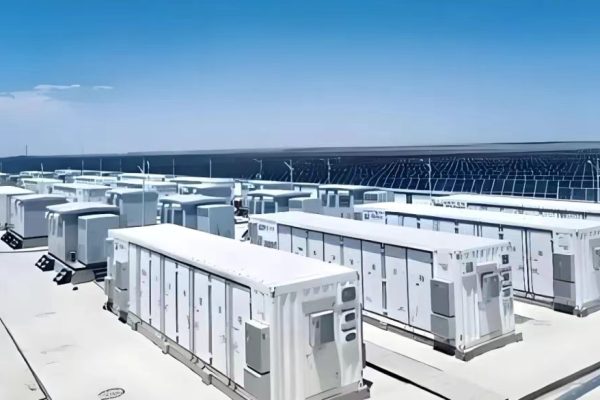
As small-scale solar + storage projects become more common — from rural homes to resort cabins to light commercial sites — one challenge continues to frustrate both new buyers and seasoned installers:
System compatibility issues.
A lithium battery that won’t charge.
An inverter that won’t recognize the BMS.
An EMS with no Modbus map.
A fuse or connector that melts under mismatch.
Most of these problems aren’t caused by bad products — but by poor system matching.
In this article, we’ll break down:
- Common sources of compatibility failure
- How to identify issues early
- Tools and strategies for solving them
- Why your guidance as a technical trade partner makes all the difference
Compatibility in PV + Storage: What Does It Actually Mean?
In any system that combines PV modules, inverters, batteries, EMS, breakers, connectors, and communication protocols — compatibility must be considered across four domains:
| Domain | What Can Go Wrong |
|---|---|
| Electrical | Voltage range mismatch, current limits, overcurrent |
| Protocol | CAN vs. RS485, incorrect mappings, timing conflicts |
| Mechanical | Connector types, cabinet dimensions, rack mismatch |
| Software/Firmware | Unsupported BMS, firmware versions, EMS conflicts |
These issues can result in system failure, underperformance, or even safety risks.
Common Compatibility Problems (and How to Prevent Them)
🔧 1. Inverter-Battery Communication Fails
Symptoms:
- Inverter won’t detect battery
- Battery shows as “unknown” or “unsupported”
- Charge/discharge stuck at 0W
Root Causes:
- Incorrect protocol (e.g., inverter expects CAN, battery uses RS485)
- Missing or outdated BMS firmware
- No pre-loaded battery profiles in inverter
How to Prevent:
- Always check the official compatibility list from the inverter brand
- Confirm protocol (CAN/RS485) and baud rate match
- If using an open protocol, get the Modbus/CAN map in advance
- Test communication before on-site deployment
🔧 2. Voltage Window Mismatch
Symptoms:
- Inverter shuts down on overvoltage or undervoltage
- Battery won’t charge or discharge fully
Root Causes:
- Battery operating voltage range does not align with inverter’s MPPT or DC input range
- Lack of voltage buffer during charge/discharge
- Temperature derating not considered
How to Prevent:
- Match inverter’s DC input range with battery’s nominal and operating voltage
- Add safety margin (especially for high C-rate discharge or cold conditions)
- Be cautious when mixing batteries from different brands
🔧 3. PV Array Misalignment with Inverter MPPT
Symptoms:
- Low solar yield
- MPPT doesn’t track correctly
- Overvoltage errors during cold mornings
Root Causes:
- PV string voltage exceeds inverter MPPT window
- Mismatched module configurations
How to Prevent:
- Use PV design tools to simulate string voltage ranges
- Consider seasonal and temperature-adjusted max voltages
- Avoid overly long or inconsistent strings
🔧 4. Incompatible Connectors and Cabling
Symptoms:
- Sparks or overheating
- Connector failure under load
- Incorrect pinout = reversed polarity
Root Causes:
- Mixed connector types (e.g., MC4 vs. Amphenol)
- Undersized wiring for current or distance
- Improper crimping or termination
How to Prevent:
- Standardize cable specs across system
- Use original manufacturer cables/connectors where possible
- Always torque test and insulation check on-site
🔧 5. Software and EMS Conflicts
Symptoms:
- System logic not obeyed (e.g., load shedding fails)
- Inverter-BMS charge logic loops or oscillates
- Unexpected shutdowns or “black start” failures
Root Causes:
- Inverter and EMS try to control the same process
- Firmware versions not matched
- Local EMS does not “understand” 3rd-party inverter logic
How to Prevent:
- Assign one device (usually EMS) as system logic master
- Test failover and priority modes
- Get EMS configuration file validated before installation
Best Practices: How to Avoid Compatibility Pitfalls
✅ 1. Start with a System Architecture Map
Before ordering any components, build a clear block diagram that shows:
- All system elements
- Voltage and current flows
- Communication links (RS485, CAN, dry contacts)
- Control priority (which device governs)
Even a basic sketch can help you spot issues early.
✅ 2. Use Products with Published Compatibility Lists
Most inverter manufacturers publish compatibility tables. For example:
- Growatt: List of approved LFP batteries
- SMA: Partner-tested EMS units
- Victron: Community-tested BMS mappings
If your selected brands are not on each other’s list, assume you will need to configure or test manually.
✅ 3. Validate Protocols Before Deployment
Don’t rely on assumptions like “It says CAN, so it must work.”
Check:
- Baud rate (e.g., 500 kbps vs. 250 kbps)
- Frame structure
- ID addressing
- CRC checks
Ask vendors for the Modbus/CAN maps and do a lab bench test.
✅ 4. Train Your Field Teams on Visual Symptoms
In practice, many compatibility issues are diagnosed by symptoms, not error codes.
Equip your installers to recognize:
- Repeating startup-shutdown cycles
- Zero-watt output despite sun and SOC
- Batteries that charge once, then stop responding
Give them reference SOPs or a quick guide for each system.
Your Role as a Technical Trade Partner
As a system provider, you are not just a component supplier. You are the first line of protection against costly mistakes.
Your responsibilities include:
- Advising customers on known compatibility pairs
- Helping debug protocol and wiring mismatches
- Pre-checking BOMs for mismatched ratings
- Documenting and archiving successful system configs
By doing this, you create real technical value — and clients will come back to you because you prevent failure, not just respond to it.