

As energy storage systems become more integrated into industrial, commercial, and remote-site applications, battery safety and redundancy have emerged as critical design priorities. Whether in a factory microgrid, telecom tower, or off-grid hybrid system, even a minor safety failure — thermal runaway, overcharge, or module imbalance — can compromise the entire operation.
Modern modular energy storage systems offer powerful scalability, but they must also maintain inherent safety and fault tolerance across each module. This article explores the technical strategies, real-world practices, and lessons learned in achieving both safety and redundancy in modular battery system design — ensuring reliable, uninterrupted operation even under challenging conditions.
1. Why Battery Safety Is Central to System Reliability
Energy storage is the backbone of modern power systems. However, the same characteristics that make batteries efficient — high energy density and fast response — also introduce potential hazards when not properly managed.
Key Safety Risks:
- Thermal runaway due to overcharge, internal short circuits, or external heating.
- Electrical imbalance between cells or modules leading to uneven stress and premature failure.
- Mechanical failure from vibration, shock, or poor enclosure design.
- Environmental exposure such as moisture, dust, or extreme temperature fluctuations.
Safety, therefore, is not only about compliance — it’s about designing predictable, self-protecting systems that maintain stability in any scenario.
2. Core Design Principles for Safe Modular Systems
a) Cell-Level Safety Management
Battery safety starts at the smallest unit — the cell. Proper selection and balancing at this level prevent cascading faults.
Design Guidelines:
- Choose chemically stable chemistries such as LiFePO₄ for applications requiring high safety margins.
- Implement cell balancing circuits to maintain voltage uniformity across series-connected cells.
- Add PTC (Positive Temperature Coefficient) devices or fuses for overcurrent protection.
- Ensure mechanical separation between cells to prevent thermal propagation.
Case Example:
A 48V, 5 kWh module used in telecom towers showed zero propagation risk in internal short testing due to integrated ceramic-coated separators and vented aluminum casing — key to maintaining safety during cell-level faults.
b) Battery Management System (BMS)
The BMS is the central nervous system of a safe battery pack. It constantly monitors electrical and thermal conditions, taking preventive or corrective actions before issues escalate.
BMS Core Functions:
- Voltage/Temperature Monitoring: Real-time protection from overcharge, deep discharge, or overheating.
- Current Control: Limiting charge/discharge rates to protect cells from stress.
- Fault Logging and Alerts: Providing remote alarms for pre-failure diagnostics.
- Cell Balancing: Ensuring uniform charge distribution to prevent localized degradation.
- Communication Protocols: Seamless data sharing with EMS or site controllers (e.g., CAN, RS485, Modbus).
Highlight:
A dual-layer BMS — with module-level and system-level controllers — offers both local fault isolation and global system coordination, dramatically improving fault containment.
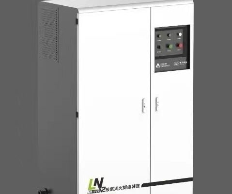
c) Mechanical and Thermal Safety
The physical design of a modular battery pack directly affects its safety performance.
Design Focus Areas:
- Enclosure: IP54 or higher for outdoor environments; corrosion-resistant materials for coastal sites.
- Thermal Management: Passive or active cooling systems depending on installation conditions.
- Fire Barriers: Non-flammable insulation layers between modules to limit propagation.
- Vibration and Shock Resistance: Especially vital in telecom and mobile storage units.
Real-World Lesson:
In a mining microgrid project, batteries exposed to continuous vibration had higher failure rates until redesigned enclosures added anti-vibration mounts and thermal isolation pads, improving lifespan by 40%.
3. Redundancy Design for Uninterrupted Operation
Safety ensures prevention; redundancy ensures continuity. Together, they form the foundation of high-reliability energy storage.
a) Module Redundancy (N+1 or N+2 Configuration)
In modular systems, redundancy means keeping one or more spare modules active or on standby to take over when a fault occurs.
Example Configuration:
- A system requiring 10 modules may include 11 or 12 total, allowing full functionality even if one module fails or is removed for maintenance.
- The BMS automatically redistributes load and isolates the failed unit.
Benefit:
Reduces unplanned downtime to near zero and allows maintenance without system shutdown.
b) Power Path Redundancy
To achieve full system availability, redundancy must also extend to power electronics and communication pathways.
Strategies:
- Dual DC bus lines: So one path remains active if the other fails.
- Redundant DC/DC converters: Ensures power regulation even under inverter or converter fault conditions.
- Controller redundancy: Dual EMS/BMS controllers for hot-standby failover.
Case Study:
In a modular ESS supporting 50 telecom towers, redundant DC/DC converters ensured continuous 48V output during one converter’s failure — preventing 120 hours of potential network downtime.
c) Communication and Monitoring Redundancy
Modern ESS rely on data communication for control and diagnostics. Any interruption here can affect performance or mask developing issues.
Design Measures:
- Dual communication channels (e.g., wired + wireless).
- Local data caching in BMS/EMS to preserve operational continuity during network loss.
- Heartbeat protocols to confirm control signal integrity.
Result:
Redundant monitoring prevents false system shutdowns and ensures fault logs remain accessible for analysis.
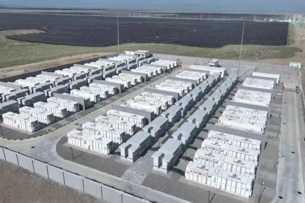
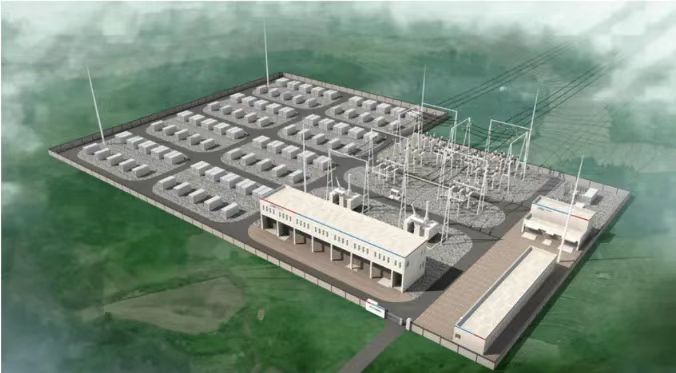
4. Practical Case Study: Modular Battery System for Industrial Microgrid
System Overview:
- Total capacity: 500 kWh (10 × 50 kWh modules)
- Chemistry: LiFePO₄
- Cooling: Hybrid passive + active air
- Redundancy: N+1 battery configuration + dual EMS
- Application: Factory microgrid with peak shaving and backup
Implementation Highlights:
- Each module equipped with local BMS and physical isolation relay.
- The system BMS monitored 200+ data points (voltage, current, temperature, SOC, SOH).
- Redundant DC bus and EMS controllers ensured uninterrupted operation during maintenance.
Results:
- System uptime: 99.8%
- No thermal incidents over 24 months
- Predictive alerts prevented two potential module failures by early replacement.
Lesson Learned:
Redundancy in both power and control paths significantly increases operational reliability — even when operating near full load under varying environmental conditions.
5. Testing and Validation for Safety and Redundancy
a) Thermal and Electrical Testing
- Overcharge, overdischarge, and short-circuit validation
- Temperature rise under full load
- Propagation resistance verification
b) Functional Safety Testing
- BMS response time under simulated failure
- Redundancy switchover validation
- Communication loss recovery
c) Long-Term Reliability Testing
- Accelerated aging and cycling
- Load shift and transient response
- Data logging for predictive maintenance model training
Insight:
Systems that undergo accelerated reliability testing (ART) achieve 2–3× fewer field failures compared to unvalidated deployments.
6. Integration with Safety Standards
When designing or deploying modular ESS, compliance with established standards ensures interoperability and safety assurance.
Relevant Standards:
- UL 1973 / IEC 62619 – Battery system safety requirements
- UL 9540 / IEC 62933 – Energy storage system integration and performance
- IEC 61508 – Functional safety of control systems
- NFPA 855 – Fire safety installation standards
Adhering to these not only ensures certification but also simplifies insurance, permitting, and end-user acceptance.
7. Key Takeaways for EPCs and Integrators
- Safety begins at the cell level – prioritize stable chemistry and protective design.
- Redundancy isn’t a luxury — it’s essential for 24/7 critical systems.
- Thermal design is a silent reliability factor — never underestimate enclosure temperature management.
- BMS sophistication defines safety and lifespan. Advanced BMS with fault isolation and predictive monitoring delivers tangible ROI.
- Testing and validation are non-negotiable. System-level endurance and propagation tests ensure peace of mind before field deployment.
Battery safety and redundancy are the twin pillars of reliable modular energy systems. By combining robust cell chemistry, intelligent BMS control, mechanical protection, and N+1 redundancy design, integrators can deliver systems that perform consistently even under stress.
As modular ESS continues to expand into telecom, industrial, and microgrid applications, projects that emphasize safety and redundancy will not only minimize operational risk but also build long-term customer trust — transforming reliability from a feature into a competitive advantage.