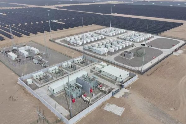
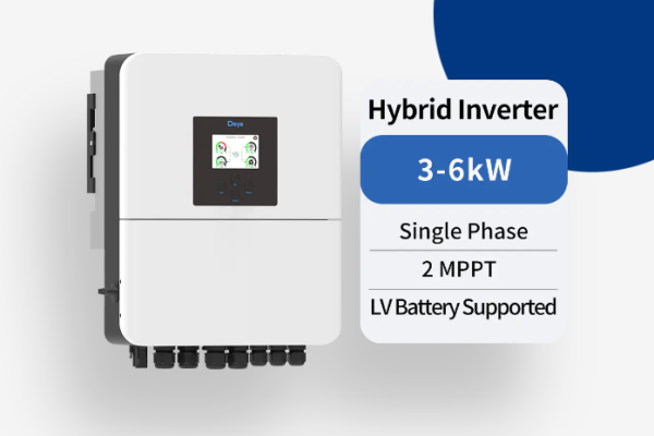
In the fast-growing Commercial & Industrial (C&I) energy storage sector, system scale and complexity are both increasing rapidly.
Unlike small residential systems, C&I projects often integrate multiple inverters, battery racks, and renewable sources—each requiring precise coordination to ensure stable performance, safety, and grid compliance.
At the center of this coordination lies the Energy Management System (EMS) — the brain that monitors, controls, and optimizes the entire operation.
However, for multi-inverter systems, communication design becomes just as critical as power design.
This article explores how EMS and communication strategies work together in multi-inverter C&I ESS, covering topologies, protocols, and best practices for scalability, reliability, and performance.
1. The Role of EMS in Multi-Inverter Energy Storage Systems
The Energy Management System (EMS) is the central controller responsible for:
- Managing power flow between grid, PV, battery, and load
- Balancing multiple inverters in parallel or distributed configurations
- Maintaining charge/discharge coordination between battery racks
- Enforcing grid code compliance (frequency response, reactive power, etc.)
- Communicating with SCADA, BMS, and utility systems
In large-scale C&I setups (e.g., 500 kWh–5 MWh), the EMS typically runs on an industrial controller or IPC, connected to field devices via RS485, CAN, or Ethernet networks.
💡 In simple terms:
The BMS protects the battery, the inverter converts energy, and the EMS decides when and how that energy moves.
2. Communication Architecture in Multi-Inverter Systems
2.1 Typical System Layers
| Layer | Device Examples | Main Protocols | Purpose |
|---|---|---|---|
| Device Layer | Inverters, battery BMS, meters | RS485, CAN | Local control and protection |
| Control Layer | EMS controller, PLC | MODBUS RTU/TCP, CAN | Coordination and scheduling |
| Supervisory Layer | SCADA, cloud platform | MODBUS TCP, MQTT, Ethernet | Remote monitoring and optimization |
In small residential systems, a single hybrid inverter often handles everything.
But in C&I or microgrid systems, multiple inverters work in parallel, and coordination requires robust communication logic to avoid:
- Power oscillations
- Unbalanced battery usage
- False alarms or disconnections
3. Common Communication Protocols in EMS Integration
RS485 / MODBUS RTU
- Most common serial communication in industrial devices
- Used for inverter and meter data acquisition
- Reliable for long-distance connections (up to 1200 m)
- Works well for systems under 1 MW
CAN Bus
- Used for real-time communication with BMS
- Enables high-speed transmission of voltage, current, and temperature data
- Provides low-latency protection signals for multi-rack coordination
MODBUS TCP / Ethernet
- Used between EMS, inverters, and SCADA
- Ideal for larger systems where multiple inverters need fast updates
- Supports hierarchical control and remote access
⚙️ Rule of thumb:
- Use CAN for battery-level safety
- Use RS485/MODBUS for inverter data
- Use Ethernet/MODBUS TCP for EMS coordination and monitoring
4. Multi-Inverter Communication Topologies
4.1 Master-Slave Configuration
One inverter acts as master and controls several slave inverters.
The master aggregates data and communicates with the EMS.
Advantages:
- Simple setup
- Easy synchronization of grid parameters
Disadvantages:
- Single point of failure (if master fails)
- Limited scalability (usually ≤10 inverters)
4.2 Distributed (Peer-to-Peer) Control
All inverters communicate with EMS directly via Ethernet or RS485.
Each inverter reports its own data, and EMS coordinates via a supervisory algorithm.
Advantages:
- Scalable to dozens of inverters
- Higher fault tolerance
- Better load balancing
Disadvantages:
- More complex communication mapping
- Requires EMS with strong computing capability
4.3 Hybrid Approach
Used in large commercial systems.
Inverters are grouped in clusters, each with a local controller that communicates upward with EMS via TCP/IP.
Advantages:
- Combines local reliability with central intelligence
- Reduces network traffic
- Modular for system expansion
🧠 Design Tip:
For systems above 500 kW, adopt a clustered EMS architecture with Ethernet backbone and local control nodes.
5. Communication Challenges in Multi-Inverter ESS
1. Address Conflicts
Multiple devices on RS485 may share the same MODBUS address.
→ Always configure unique IDs and label cables clearly.
2. Baud Rate Mismatch
Mismatched communication speed (e.g., 9600 bps vs. 19200 bps) leads to signal loss.
→ Standardize baud rate across all devices.
3. Signal Interference
Long cable runs and improper grounding can cause noise.
→ Use shielded twisted-pair cables and proper terminations.
4. Data Mapping Inconsistency
Different manufacturers may use custom MODBUS registers.
→ Verify register maps during design stage, not during commissioning.
5. Latency and Synchronization
In multi-inverter setups, communication delays can cause phase mismatches or unbalanced loads.
→ Prioritize Ethernet communication for time-sensitive control.
6. EMS Control Functions for Multi-Inverter Systems
A. Power Sharing
EMS ensures all inverters share active and reactive power equally based on load and battery conditions.
B. Battery Balancing
In multi-rack systems, EMS monitors individual SOC levels and dispatches charge/discharge accordingly.
C. Peak Shaving and Load Shifting
By scheduling energy use, EMS optimizes demand charges and time-of-use tariffs.
D. Grid Interaction
Implements frequency and voltage regulation, and handles zero export or power factor control.
E. Fault Management
EMS can isolate faulty inverters or battery racks while keeping the rest of the system operational.
🔋 Example:
In a 1 MWh factory ESS with 8 hybrid inverters, EMS monitors each unit’s power flow and directs energy dispatch for maximum battery life and minimal downtime.
7. Practical Communication Design Tips
- Use industrial-grade Ethernet switches with surge protection.
- Segment communication networks (BMS, inverter, SCADA) to prevent data congestion.
- Label each device port and maintain a communication diagram in documentation.
- Ensure protocol consistency (e.g., MODBUS RTU vs. MODBUS TCP).
- Test communication stability before loading full power.
- Use redundancy—backup Ethernet or RS485 links for critical nodes.
- Monitor communication logs in EMS to detect anomalies early.
8. Example Configuration: 1 MWh C&I ESS
| Component | Quantity | Communication | Notes |
|---|---|---|---|
| Hybrid Inverters (100 kW each) | 10 | Ethernet (MODBUS TCP) | Parallel grid-tied operation |
| Battery Racks (102 kWh each) | 10 | CAN | Linked via BMS |
| EMS Controller | 1 | TCP/IP | Controls all inverters |
| Smart Meter | 1 | RS485 (MODBUS RTU) | For grid import/export monitoring |
| SCADA Gateway | 1 | Ethernet | Remote monitoring via cloud |
⚡ With proper EMS design, this setup achieves:
- 98% inverter coordination efficiency
- < 50 ms command latency
- Automatic load balancing and real-time response
9. EMS Software Considerations
When selecting or designing EMS software for multi-inverter C&I systems, ensure it includes:
- Real-time data acquisition (1s intervals)
- Custom MODBUS register mapping tools
- Automatic inverter detection and grouping
- State-of-Charge balancing logic
- Event and alarm management
- Cloud synchronization via MQTT or API
- Remote firmware update support
🧩 The most flexible EMS platforms support both MODBUS and CAN gateways, enabling integration of mixed-brand components.
10. Future Trends in EMS and Communication
- Edge EMS Controllers: Local AI-based control reduces dependency on cloud servers.
- OPC UA / IEC 61850 Integration: Standardized communication with utilities and microgrids.
- Wireless Mesh Networks: For distributed systems where cabling is costly.
- Cybersecurity Layers: TLS encryption and VPN channels for data protection.
- Cloud-EMS Hybrid Models: Combining local control with cloud analytics for predictive maintenance.
Designing communication strategies for multi-inverter C&I energy storage systems is about balancing speed, reliability, and scalability.
An efficient EMS architecture not only ensures real-time data exchange but also maximizes energy efficiency, safety, and system uptime.
✅ Key Takeaways:
- Combine CAN, RS485, and Ethernet intelligently.
- Use clustered EMS design for scalability.
- Verify protocol compatibility before project execution.
- Prioritize redundant communication paths for mission-critical systems.
As commercial energy storage continues to scale up, mastering EMS communication design will be the key differentiator between a stable, intelligent system and a costly integration challenge.
