When buyers plan a PV + Energy Storage System (ESS), they often focus on the main hardware — solar panels, batteries, and inverters.
However, experienced engineers know that the Balance of System (BOS) components determine the project’s reliability, efficiency, and long-term safety.
In this guide, we’ll break down the key BOS elements in solar + storage systems, their functions, common mistakes during selection, and what international buyers should check before placing an order.
1. What Is “BOS” in PV+Storage Projects?
Balance of System (BOS) refers to all components other than PV modules and batteries that are necessary for the installation and operation of the system.
In PV+ESS systems, BOS typically includes:
- Mounting structures
- Cables and connectors
- DC/AC combiner boxes
- Protection devices (breakers, fuses, SPD)
- Monitoring and communication equipment
- Switchgear, transformers, and EMS (Energy Management System)
💡 Think of BOS as the “circulatory system” of a solar + storage project — invisible, but vital.
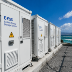
2. Importance of BOS in Energy Storage Systems
While PV panels and batteries define capacity, BOS defines performance.
Key BOS functions:
- Ensure safe current flow between PV, inverter, and battery
- Maintain system efficiency and minimize energy loss
- Provide protection against overcurrent, lightning, and reverse polarity
- Enable monitoring and control for optimal system operation
Without properly selected BOS components, even a premium inverter and battery can fail to deliver expected performance.
3. PV Side BOS Components
a. Mounting Structure
- Material: Hot-dip galvanized steel or aluminum alloy
- Function: Fix solar modules at optimal tilt angle
- Buyer Tips: Confirm corrosion protection (≥80μm coating for coastal regions)
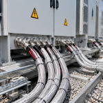
b. PV Cables
- Standard: TÜV / IEC 62930
- Key Specs: 1500V DC, double insulation, UV-resistant
- Common Mistake: Using indoor-rated cables outdoors → insulation cracking
c. MC4 Connectors
- Purpose: Quick and safe PV string connections
- Buyer Tip: Avoid mixing brands — mismatched plugs may cause overheating.
d. DC Combiner Box
- Collects multiple PV strings and provides surge & fuse protection.
- Should include SPD, fuse holders, and isolators.
- Best Practice: IP65 waterproof, with clear wiring diagram inside lid.
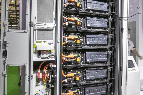
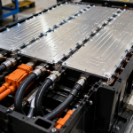
4. Battery Side BOS Components
a. Battery Cables and Lugs
- Must handle high current (often >200A for large systems).
- Use tinned copper conductors and heat-shrink insulation.
- Tip: Verify torque value and terminal labeling for each module.
b. Battery Breaker & Fuse
- Function: Protect against short-circuit and overcurrent.
- Standard: DC-rated breaker (e.g., DC1000V, 250A).
- Buyer Tip: Choose reputable brands like Eaton, ABB, or Chint for reliability.
c. BMS Communication Wiring
- Links battery to inverter via CAN / RS485 / Modbus.
- Improper wiring or pinout mismatch is one of the top 3 causes of commissioning delays.
5. AC Side BOS Components
a. AC Breakers and Contactors
- Protect inverters from overcurrent and allow safe isolation.
- For hybrid systems, choose AC-rated contactors compatible with inverter surge current.
b. Distribution Box or AC Combiner
- Combines output from multiple inverters into one grid connection.
- Should include surge protection and isolation switches.
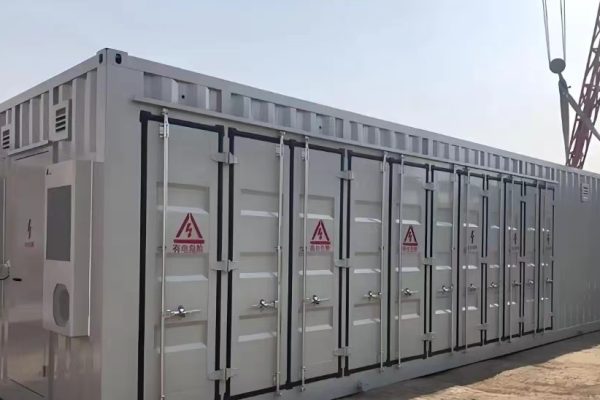
c. Transformer (for C&I or Utility ESS)
- Steps up inverter output (400V → 11kV, etc.) for grid connection.
- Dry-type transformers preferred for indoor installations.
6. Protection and Safety Components
| Protection Device | Purpose | Location | Notes |
|---|---|---|---|
| Surge Protection Device (SPD) | Protect from lightning surges | PV side, AC side | Use Type II SPD for most sites |
| Fuses | Overcurrent protection | PV strings, battery bus | Always use DC-rated types |
| Isolator Switch | Manual disconnect | PV, battery, AC output | Must be lockable |
| Grounding System | Personnel and equipment safety | Entire system | Verify continuity <1Ω |
⚡ Every BOS protection layer adds one level of resilience to your system.
7. Communication and Monitoring
a. Data Logger / Gateway
Collects inverter, battery, and EMS data for cloud monitoring.
b. Energy Management System (EMS)
- Controls power flow between PV, grid, and battery.
- Implements time-of-use optimization and peak shaving.
- Should support remote firmware update and open communication protocols.
c. SCADA Interface (for large systems)
Used for integration with site-level control or grid dispatch.
📡 Make sure your inverter, battery, and EMS share compatible communication protocols (Modbus TCP, RS485, or CAN).
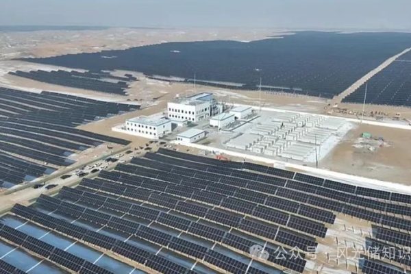
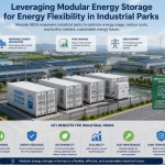
8. BOS in Hybrid PV+Storage Projects
Hybrid systems require extra coordination between PV and ESS.
That means both DC and AC BOS components must be properly designed.
Common integration points:
- DC combiner connects PV and battery to shared inverter input
- Common AC bus connects grid and load
- Shared grounding system and protection devices
🧩 Mistake to avoid: Using PV combiner boxes without DC isolation between PV and battery circuits — may cause backfeed or inverter alarm.
9. Installation and Commissioning Considerations
- Use pre-labeled cables to minimize wiring errors
- Keep DC and AC routes separated to avoid interference
- Verify torque values for all terminal connections
- Confirm polarity before energizing PV or battery circuits
- Record IR values (insulation resistance) for acceptance report
🧰 A well-documented BOS layout simplifies future maintenance and troubleshooting.
10. Quality and Certification
Buyers should ensure BOS components comply with:
- IEC / UL standards for voltage and current ratings
- IP rating (≥IP65 for outdoor use)
- Flame-retardant standards (e.g., UL94-V0 for plastic parts)
- CE / RoHS / UKCA marks for exports
🏷️ Ask suppliers to include a BOS component list with all certificates before shipment.
11. Cost Breakdown: BOS’s Real Impact
Though often overlooked, BOS typically accounts for 20–30% of total system cost.
| Project Type | BOS Share of Total Cost |
|---|---|
| Residential (5–10 kW) | 25–35% |
| Commercial (50–200 kW) | 20–25% |
| Utility (>1 MW) | 15–20% |
Investing in high-quality BOS components increases efficiency and reduces maintenance — a small upfront cost that protects long-term returns.
12. Example: 100 kW PV + 200 kWh ESS System
Configuration:
- PV Array: 100 kW
- Hybrid Inverter: 100 kW
- Battery: 200 kWh LFP
- BOS Includes:
- 2× DC combiner boxes
- 1× AC distribution cabinet
- 1× EMS + Data Logger
- SPD, breakers, and grounding kit
Result:
- System efficiency improved by 1.5%
- Faster installation time by 20% using pre-assembled BOS kits
- Lower maintenance due to modular cable design
In every PV+ESS project, BOS components are the silent foundation of reliability.
They may not be the most visible items in the quotation, but they determine whether your system performs smoothly for years.
By paying attention to BOS quality, compatibility, and certification, you ensure that:
✅ Energy flows safely and efficiently
✅ Installation is faster and easier
✅ Long-term O&M costs are reduced
⚙️ Remember — premium BOS is not an expense; it’s a form of insurance for your investment.