

A Practical Guide for Reliable Solar and Off-Grid Energy Systems
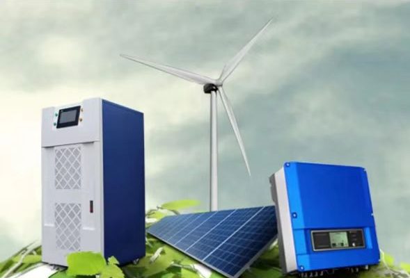
Whether you’re building a solar energy system, a hybrid storage setup, or a backup power solution, one of the most important design steps is ensuring that your inverter and battery are properly matched.
A mismatch between the two can lead to poor efficiency, inverter shutdowns, or even battery damage.
This article explains — with open and verifiable data — how to select and match inverters and batteries for small to medium-scale systems (from 1 kW to 100 kW), focusing on voltage compatibility, current ratings, battery chemistry, and energy capacity planning.
1. Understanding the Role of Each Component
Before matching, it’s important to review the core function of each:
- Battery: Stores DC energy. The battery voltage defines the system’s DC bus (commonly 12 V, 24 V, 48 V, or higher for commercial systems).
- Inverter: Converts DC power to AC for loads (e.g., 120/240 V single-phase or 380/400 V three-phase).
A mismatch between the inverter’s DC input range and the battery’s voltage can cause undervoltage or overvoltage shutdowns.
2. Step One: Match the Voltage
Battery System Voltage vs Inverter DC Input
The most fundamental rule is:
The nominal DC voltage of the battery bank must match the inverter’s DC input range.
| System Type | Typical Battery Bank | Inverter DC Range | Common Use |
|---|---|---|---|
| Small off-grid | 12 V | 10.5–15 V | RVs, boats, tiny systems |
| Medium hybrid | 24 V | 21–32 V | Home solar setups |
| Larger residential | 48 V | 42–60 V | Solar + storage |
| Commercial / Industrial | 96–600 V | 80–650 V | Microgrids, UPS, EV stations |
If the inverter requires 48 V nominal, your battery bank (series of cells or modules) must produce about 48 V DC nominally (e.g., 16 LiFePO₄ cells × 3.2 V = 51.2 V).
3. Step Two: Check the Inverter Input Current
Each inverter has a maximum DC current rating, which must not be exceeded during operation.
Formula for current draw: I=PV×ηI = \frac{P}{V \times \eta}I=V×ηP
where
- P = inverter output power (W)
- V = battery voltage (V)
- η = inverter efficiency (usually 0.9–0.95)
Example:
For a 5000 W inverter on a 48 V battery at 92% efficiency: I=500048×0.92≈113AI = \frac{5000}{48 \times 0.92} ≈ 113 AI=48×0.925000≈113A
Thus, your battery and cables must handle at least 120 A continuously, with surge tolerance up to 150 A.
💡 Tip: Always oversize your cable and fuse by at least 20–25% to account for start-up surges.
4. Step Three: Consider Battery Chemistry Compatibility
Different battery chemistries require different charging voltages and control protocols.
Always check whether your inverter (or its charge controller) supports your specific chemistry.
| Chemistry | Typical Cell Voltage | Common Nominal | BMS Required | Notes |
|---|---|---|---|---|
| Lead-acid (AGM/GEL) | 2 V | 12/24/48 V | No | Simple but lower efficiency |
| LiFePO₄ | 3.2 V | 12.8/25.6/51.2 V | Yes | Stable and long-life |
| NMC / LFP modules | 3.6–3.7 V | 48–400 V | Yes | Used in EV and commercial storage |
Key consideration:
If your inverter supports CAN/RS485 communication, match it with a smart BMS (Battery Management System) from the same brand or a compatible protocol (e.g., Pylontech, BYD, LG Chem).
This enables voltage, SOC, and current control synchronization — critical for lithium batteries.
5. Step Four: Balance Capacity and Power
Energy (kWh) vs Power (kW)
- Energy capacity (kWh) = how long the system can supply power.
- Power rating (kW) = how much power can be delivered instantly.
To maintain healthy operation, the battery’s discharge current limit must exceed the inverter’s continuous draw.
Example:
- 48 V × 200 Ah battery = 9.6 kWh
- Continuous discharge current = 100 A
- If inverter draws 120 A (≈ 5.5 kW), the battery may overheat or shut down early.
→ Solution: use a higher-capacity bank (e.g., 48 V × 300 Ah) or parallel two 48 V × 150 Ah packs.
Rule of Thumb
Battery (Ah)=Inverter Power (W)×Backup HoursBattery Voltage (V)×DOD\text{Battery (Ah)} = \frac{\text{Inverter Power (W)} \times \text{Backup Hours}}{\text{Battery Voltage (V)} \times \text{DOD}}Battery (Ah)=Battery Voltage (V)×DODInverter Power (W)×Backup Hours
For a 5 kW inverter, 48 V system, 3 h backup, and 80% usable DOD: Battery=5000×348×0.8≈390Ah\text{Battery} = \frac{5000 \times 3}{48 \times 0.8} ≈ 390 AhBattery=48×0.85000×3≈390Ah
So, you’d need about 48 V × 400 Ah = 19.2 kWh total capacity.
6. Step Five: Mind the Surge and Peak Loads
Inverters can briefly deliver 2–3× their rated power for milliseconds to start motors or compressors.
Your battery must handle these surge currents without voltage drop.
| Load Type | Surge Multiplier | Example |
|---|---|---|
| Resistive (LED, heater) | 1× | Stable |
| Inductive (fridge, fan) | 2–3× | 500 W → 1.5 kW surge |
| Motor / Compressor | 3–6× | 1 kW → 3–6 kW |
Lithium batteries (especially LiFePO₄) can handle high surge currents better than AGM lead-acid, which suffer voltage sag.
✅ Pro Tip: Choose a battery whose maximum discharge current ≥ 2× inverter rated current.
7. Step Six: Consider System Efficiency
Each conversion stage (battery → inverter → load) introduces losses.
Real-world inverter efficiency ranges between 85–95% depending on load and waveform quality.
| Load % | Typical Efficiency |
|---|---|
| 25% | 88% |
| 50% | 92% |
| 75% | 94% |
| 100% | 93% |
To optimize runtime:
- Avoid oversizing the inverter (efficiency drops at low load).
- Use MPPT charge controllers integrated with hybrid inverters to minimize conversion losses.
8. Step Seven: Charging Voltage and BMS Communication
For lithium systems, it’s critical that the inverter/charger charging profile matches the battery’s recommended voltage.
| Chemistry | Charge Voltage (per cell) | 48 V Pack (16 cells) | Notes |
|---|---|---|---|
| Lead-acid | 2.35 V | 56.4 V | Float/absorb cycles |
| LiFePO₄ | 3.45 V | 55.2 V | Constant voltage, BMS cutoff |
| NMC | 4.2 V | 67.2 V | High voltage, needs strict BMS control |
If the inverter cannot precisely regulate voltage, it may overcharge lithium cells, leading to thermal imbalance.
Smart inverters (Growatt, Victron, Deye, SMA, etc.) now support CAN-bus protocols that auto-adjust based on battery feedback.
9. Step Eight: Cable Sizing and Protection
Improper cabling can cause voltage drops, overheating, and inefficiency.
Voltage drop formula: Vdrop=I×R=2×L×I×ρAV_{drop} = I \times R = \frac{2 \times L \times I \times \rho}{A}Vdrop=I×R=A2×L×I×ρ
where ρ = 0.0175 Ω·mm²/m for copper.
Keep total voltage drop <2% between battery and inverter.
| Current (A) | Cable Length (m) | Recommended Cable (mm²) |
|---|---|---|
| 60 | 3 | 16 |
| 100 | 3 | 25 |
| 150 | 3 | 35 |
| 200 | 3 | 50 |
Add fuses or DC breakers near the battery positive terminal, rated at 1.25× the expected current.
10. Step Nine: Consider Inverter Type
Different inverter topologies have different requirements for battery compatibility:
| Type | Function | Battery Requirements |
|---|---|---|
| Pure Sine Wave | Produces grid-like waveform | Stable voltage, low ripple |
| Modified Sine Wave | Budget option | High ripple current—shortens battery life |
| Hybrid Inverter | Integrates MPPT + grid | Needs smart BMS link |
| Off-Grid Inverter | Isolated system | Tolerant but needs precise DC matching |
For sensitive electronics or lithium systems, pure sine wave hybrid inverters are strongly recommended.
11. System Example: 10 kW Hybrid Solar Setup
| Parameter | Design Choice | Notes |
|---|---|---|
| Inverter | 10 kW hybrid inverter (48 V DC input) | Efficiency > 94% |
| Battery | 48 V × 400 Ah LiFePO₄ (20 kWh) | Max discharge = 200 A |
| DC Current | ≈ 210 A at full load | Cable ≥ 50 mm² |
| PV Input | 12 kW array (400 V MPPT) | Ensures full charge in ≤ 5 h |
| Runtime | ~3.5 h at full load | Depth of discharge = 80% |
| BMS | CAN/RS485 linked to inverter | Smart communication |
This combination maintains stable DC voltage, high efficiency, and safe thermal performance under both peak and steady loads.
12. Common Mistakes to Avoid
- ⚠ Using 12 V batteries with 48 V inverters — voltage mismatch causes immediate shutdown.
- ⚠ Underrated cables — lead to overheating or inverter fault codes.
- ⚠ Ignoring battery discharge limits — shortens lifespan or triggers BMS cutoff.
- ⚠ Mixing old and new batteries — causes imbalance and uneven aging.
- ⚠ Oversizing the inverter for small loads — reduces overall efficiency.
13. Maintenance and Monitoring
Modern systems benefit from remote monitoring and smart management:
- BMS communication: Tracks cell voltage, temperature, and state of charge (SOC).
- Inverter monitoring apps: Provide real-time power flow and battery health.
- Periodic calibration: Rebalance lithium packs every 6–12 months for long-term stability.
Expected lifetimes:
- LiFePO₄ batteries: 4000–6000 cycles (10–15 years).
- Lead-acid: 500–800 cycles (2–4 years).
- Modern hybrid inverters: 10–12 years with regular firmware updates.
14. Summary Table: Matching Guide
| Parameter | Checkpoint | Why It Matters |
|---|---|---|
| Voltage | Must match inverter DC input | Prevents under/over-voltage trips |
| Current | Battery ≥ inverter current draw | Avoids overload |
| Chemistry | Supported by inverter firmware | Ensures proper charging |
| Capacity | Matches load runtime | Determines autonomy |
| Communication | CAN/RS485 optional | Improves control and safety |
| Cables & Fuses | Properly rated | Prevents power loss and overheating |
Matching inverters and batteries is not just a voltage check — it’s a balance between electrical performance, battery chemistry, and system design.
A well-matched system will:
- Deliver higher efficiency (90–95%)
- Extend battery life by 20–40%
- Improve system stability and safety
By understanding these parameters — voltage, current, chemistry, and communication — installers and engineers can design durable, scalable, and safe solar-plus-storage systems for both residential and commercial applications.