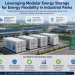
How to Design Scalable Energy Storage Solutions for Commercial & Industrial Users
As the global energy transition accelerates, Commercial and Industrial (C&I) users increasingly rely on battery energy storage systems (BESS) to reduce electricity costs, manage peak demand, and ensure business continuity.
While large-scale installations (1MWh+) attract headlines, the sub-500kWh segment is where most real commercial adoption occurs — especially in factories, logistics centers, data facilities, and campuses.
This article explores how to design flexible, modular C&I storage systems under 500kWh, balancing technical reliability, financial performance, and future scalability.
1. Why Focus on Sub-500kWh C&I Systems
Energy storage under 500kWh plays a vital role for:
- Medium factories managing peak loads of 100–300kW
- Hotels, schools, hospitals seeking backup and demand charge reduction
- Office parks and microgrids integrating solar PV
- EV charging stations stabilizing power usage
Key Advantages:
- Easier permitting and installation
- Lower initial investment
- Shorter payback period (3–5 years)
- Scalable through modular expansion
These systems serve as the backbone of distributed energy networks — bridging the gap between residential and utility-scale storage.
2. Defining “Flexible” in Storage Design
In modern energy projects, flexibility means more than just modular hardware. It includes:
- Modular capacity scaling — Expand from 100kWh → 500kWh easily
- Multi-mode operation — Grid-tied, off-grid, or hybrid
- Technology openness — Compatible with different PV, inverters, and EMS
- Deployment flexibility — Indoor racks, outdoor cabinets, or container systems
- Software flexibility — Customizable control logic for TOU, peak shaving, or backup
A flexible system can adapt to load changes and business growth without major redesigns.
3. Step 1 – Define the Use Case
C&I storage designs start with a clear understanding of application scenarios.
| Use Case | Primary Goal | Typical Battery Capacity |
|---|---|---|
| Peak shaving / demand management | Reduce grid demand charges | 100–300kWh |
| Solar self-consumption | Maximize onsite PV use | 200–400kWh |
| Backup power / resilience | Maintain critical loads | 300–500kWh |
| Load shifting / TOU optimization | Charge at night, discharge at peak | 200–500kWh |
A 250kWh system can often cover 50–70% of a factory’s demand charge needs or power critical operations for several hours during an outage.
4. Step 2 – Choose the System Architecture
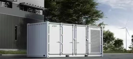
Option A: Integrated Outdoor Cabinet Systems (50–300kWh)
- Compact, IP54-rated all-in-one design
- Pre-integrated with inverter, BMS, and EMS
- Ideal for space-limited or rapid-deployment projects
- Examples: 100kWh and 215kWh outdoor cabinets
Option B: Rack-Based Indoor Systems (100–500kWh)
- Installed in dedicated battery rooms
- Customizable layout and cooling options
- Easier maintenance and scalability
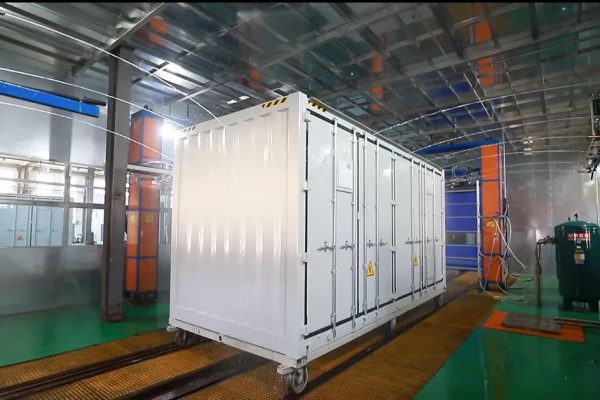
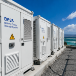
Option C: Containerized Systems (250–500kWh)
- 20-ft container with integrated HVAC, fire suppression, and inverter
- Suitable for outdoor industrial sites
- Best choice for scalability and safety
Selection depends on available space, installation environment, and local regulations.
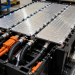
5. Step 3 – Battery Chemistry Selection
Battery chemistry determines system safety, performance, and cost.
| Chemistry | Advantages | Considerations |
|---|---|---|
| LFP (LiFePO₄) | High safety, long cycle life (>6000), low degradation | Slightly heavier, moderate cost |
| NMC | Higher energy density | Requires stricter safety management |
| LTO | Extreme temperature performance | High cost, niche use |
For sub-500kWh C&I systems, LFP is the industry standard due to safety, thermal stability, and long service life.
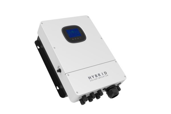
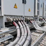
6. Step 4 – Inverter and PCS Configuration
The Power Conversion System (PCS) manages bidirectional power flow between grid, battery, and loads.
Sizing Guidelines:
- Rated Power: Typically 50%–100% of battery C-rate
- Example: 250kWh battery → 125kW PCS
- Voltage Range: 600–1000V DC
- Conversion Efficiency: ≥97%
Operation Modes:
- Grid-connected peak shaving
- PV + storage hybrid
- Backup / islanding mode
- Black start capability (optional)
Hybrid PCS units that combine solar MPPT inputs simplify wiring and reduce CAPEX for PV + Storage applications.
7. Step 5 – Energy Management System (EMS)
The EMS coordinates real-time operation for performance and profitability.
EMS Core Functions:
- Demand management: Predict and flatten load peaks
- TOU optimization: Maximize charge/discharge scheduling
- SOC management: Extend battery life
- Data visualization: Remote monitoring via web or app
- Grid communication: Modbus/TCP, CAN, or IEC 61850 protocols
For multi-site users, cloud-based EMS allows unified control across factories or branches.
8. Step 6 – Safety and Compliance
Safety is non-negotiable for C&I systems.
Key Design Standards:
- IEC 62619 / UL 1973: Battery cell and module safety
- UL 9540 / IEC 62933: Complete system certification
- NFPA 855: Fire protection design
- IEC 62109: PCS electrical safety
Core Safety Features:
- Integrated BMS (cell balancing, temperature control)
- Fire suppression (aerosol or clean agent)
- Thermal monitoring (per-rack sensors)
- Insulation and short-circuit detection
- Emergency stop & remote shutdown
For outdoor projects, consider container systems with active cooling + multi-zone fire isolation.
9. Step 7 – Scalability and Modularity
Modularity allows system growth as demand increases.
Example Expansion Path:
| Stage | System Capacity | PCS Rating | Description |
|---|---|---|---|
| Phase 1 | 100kWh | 50kW | Peak shaving for small loads |
| Phase 2 | 250kWh | 100kW | Add PV self-consumption |
| Phase 3 | 500kWh | 200kW | Integrate EV chargers & microgrid |
Use standardized 50–100kWh modules with compatible communication interfaces to ensure plug-and-play scalability.
10. Step 8 – Cooling and Environmental Design
Thermal management directly affects system lifespan and safety.
| Environment | Cooling Method | Notes |
|---|---|---|
| Indoor | Forced air cooling | Low cost, simple maintenance |
| Outdoor cabinet | Air conditioning / liquid cooling | Maintain <35°C ambient |
| Containerized | Active HVAC with redundancy | Recommended for 250kWh+ |
Keep temperature deviation between racks <3°C to prevent uneven aging.
11. Step 9 – System Performance Example
Case Study: 300kWh / 150kW Factory Storage System
| Parameter | Value |
|---|---|
| Battery Type | LFP, 300kWh (15 racks × 20kWh) |
| PCS | 150kW hybrid inverter |
| Application | Peak shaving + PV optimization |
| Daily cycle depth | 60–70% |
| Round-trip efficiency | 92% |
| Savings | 20–30% reduction in electricity bills |
| Payback | 3.5–4 years |
The system automatically charges during low-tariff hours (night) and discharges during daytime peaks, reducing monthly demand charges significantly.
12. Step 10 – Cost and ROI Estimation
Typical Cost Breakdown (2025 Estimate)
| Component | Cost (USD/kWh) | Total (for 300kWh) |
|---|---|---|
| Battery Pack (LFP) | $200–250 | $60,000–75,000 |
| PCS / Inverter | $150/kW | $22,500 |
| EMS + Controls | $5,000–10,000 | |
| Installation & BOS | $15,000–25,000 | |
| Total | $100,000–130,000 |
Financial Performance
- Annual savings: $25,000–35,000
- Payback period: 3–5 years
- System lifetime: 10–15 years
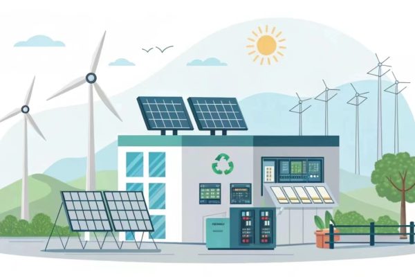
13. Step 11 – Integration with PV and EV Infrastructure
Flexible 500kWh systems can be hybridized with renewable assets:
- PV Integration: Charge batteries directly from rooftop solar
- EV Charging Support: Supply stable DC bus power to fast chargers
- Microgrid Mode: Operate independently during grid outages
Hybrid control strategies ensure zero-export, self-consumption, or islanding according to user needs.
14. Step 12 – Operation & Maintenance (O&M)
A robust O&M plan extends lifespan and ensures reliability.
Key Tasks:
- Monthly checks: Voltage, temperature, insulation resistance
- Quarterly software updates: EMS and PCS firmware
- Annual inspections: Cable connections, air filters, BMS data logs
- Predictive maintenance: Use AI analytics to detect early faults
Cloud-based diagnostics can reduce O&M costs by up to 30% compared with manual inspection.
15. Long-Term Benefits of Sub-500kWh C&I Systems
| Benefit | Impact |
|---|---|
| Energy Cost Reduction | Peak shaving, load shifting |
| Backup Power Security | Prevent downtime losses |
| Grid Independence | Stabilize operations |
| Environmental Compliance | Support ESG and carbon neutrality |
| Future Expandability | Modular and upgradeable design |
These systems allow businesses to transition gradually from grid dependency to energy autonomy — without major upfront investments.
Building flexible C&I energy storage systems under 500kWh is no longer a niche engineering project — it’s a mainstream commercial solution.
The key is modularity, standardization, and intelligent control.
By combining LFP batteries, hybrid PCS, and cloud-based EMS, integrators can deliver systems that scale from 100kWh to 500kWh seamlessly.
Such systems empower C&I users to:
- Cut operational costs,
- Improve energy resilience, and
- Prepare for renewable integration.
In the era of distributed energy, flexible sub-500kWh storage is the most practical and profitable step toward a smarter, more stable energy future.