
Practical Guidelines for Safer, Smarter Small-Scale Energy Storage Integration
Why Multi-Module Wiring Matters
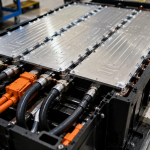
In small to medium-sized energy storage systems, especially in the 5–30kWh range, modular battery setups are increasingly popular. Instead of using one large battery, you may use 2, 3, or even more battery modules in parallel — often connected to a single hybrid inverter.
Modular systems offer flexibility, scalability, and easier logistics. But improper wiring between battery modules can cause:
- Imbalanced currents
- Uneven state of charge (SoC)
- Overheating or premature aging
- Communication errors
- System failures
In this article, we’ll walk you through the correct way to wire multiple battery modules, and highlight the most common mistakes to avoid.
1. The Most Common Multi-Module Configurations
🔹 Parallel Wiring of Batteries
Most modular systems connect battery modules in parallel, while maintaining the same voltage level (e.g., 48V):
- 3 × 48V 100Ah → 48V 300Ah = 14.4kWh system
- Each module shares the current load
This allows expansion and redundancy, but requires careful attention to wiring symmetry and balancing.
2. Key “Do’s” in Multi-Module Wiring
✅ Do Use Identical Cable Lengths and Sizes
This is the #1 rule.
Always use equal-length cables for each battery module’s positive and negative terminals.
Why it matters: Different cable lengths or gauges result in different resistance. This causes uneven current distribution, meaning some batteries discharge or charge faster than others — leading to SoC imbalance and lifespan reduction.
✅ Do Connect to a Common Busbar
This ensures equal access to the inverter load and balances currents.
✅ Do Use Proper Fusing and Disconnects
Each module should have its own fuse or breaker for protection, especially in systems above 100A total current.
Also install:
- A DC main disconnect switch
- Surge protection if needed
- Optional battery isolators for maintenance
✅ Do Follow Manufacturer Guidelines
Always refer to your battery supplier’s documentation. Some LFP systems may require:
- Specific pre-charge steps
- Shared BMS master-slave roles
- Series-parallel restrictions
Following “generic” practices may void your warranty or cause safety issues.
3. The Most Common “Don’ts” in Multi-Module Wiring
❌ Don’t Daisy Chain Battery Modules
Avoid connecting battery 1 to battery 2, then battery 2 to battery 3, and so on — this introduces resistance imbalance and cascading failure risks.
This setup creates unequal current paths. Modules at the ends will behave differently from those in the middle.
❌ Don’t Mix Old and New Batteries
Mixing new and aged batteries can result in SoC mismatch, increased degradation, and possible BMS shutdowns.
If expansion is needed later, use identical model and production batch batteries and follow balancing procedures.
❌ Don’t Forget Pre-Charge or BMS Sync
When connecting batteries to an inverter or busbar:
- Pre-charge large capacitors to avoid surge current
- Ensure all BMS units are in compatible communication (if CAN/RS485 protocols are involved)
- Follow the correct power-on order: often battery → inverter → loads
❌ Don’t Undersize Your Cabling
A common mistake in cost-sensitive projects is undersizing the cable between the battery and inverter.
Use cable sizing tools or follow this simple rule of thumb:
For every 1kW of DC power at 48V → ~21A
So a 5kW inverter = ~105A = needs at least 35mm² copper cable
Always check allowable current rating and temperature rise for your specific cable type.
4. Communication Wiring: Often Overlooked, Often a Problem
If your battery modules communicate with each other or with the inverter (e.g., via CAN or RS485):
✅ Use Shielded Cables
This reduces EMI (electromagnetic interference) — critical when batteries sit near AC cables.
✅ Maintain Proper Termination
Many RS485/CAN setups require 120-ohm termination resistors at the ends. Check your user manual.
✅ Set Unique IDs for Each Module
Avoid conflicts by assigning each module a different communication address or DIP switch setting.
5. Safety Considerations
Even in small systems, battery wiring carries serious energy. Always:
- Use insulated lugs and crimp tools
- Label all DC cables clearly (especially when hidden in cabinets)
- Avoid running DC cables in parallel with AC wires
- Include fire-resistant conduits or trunking in indoor installations
6. Typical Multi-Module Wiring Diagram (5–15kWh System)
Here’s what a healthy setup might include:
- 3 x 48V 100Ah LFP modules
- Each with 150A fuse
- Connected to positive and negative busbars with identical 25mm² cables
- 250A main breaker to inverter
- CAN communication linked to hybrid inverter
- AC output to sub-panel for backup loads
This setup supports:
- Scalable capacity
- Maintenance access to each module
- Clean power delivery under load
7. Commissioning Checklist
Before powering up:
✅ All cables tight and torqued
✅ No polarity reversal
✅ Communication connections confirmed
✅ Pre-charge circuit used (if needed)
✅ Fuses and disconnects installed
✅ Inverter settings match battery specs (voltage window, max charge/discharge current)
8. Field Lessons from Installers
💬 “The moment we used unequal cables, one battery ran hot and failed in under a year.”
💬 “Adding the third module worked electrically, but the CAN ID conflicted. We had to reassign addresses to get it stable.”
💬 “After fixing the daisy-chain layout and switching to busbars, our system finally stabilized — no more random BMS shutdowns.”
Wire It Right, or It Fights You Later
Multi-module systems are a great choice — when wired correctly. They offer flexibility, modularity, and cost efficiency. But poor wiring can sabotage performance, reduce safety, or cause nuisance failures.
As a buyer or installer, you can avoid these issues by:
- Following symmetry rules
- Avoiding daisy-chaining
- Paying attention to communication wiring
- Sizing cables and protections properly
Get the wiring right upfront, and your system will reward you with years of stable operation.